Creating and editing items
Generalities
This section describes in details the software features allowing you to create or edit technical objects.
Method of instantiating objects in the scene
The various libraries contain elements (also known as 'assets') that you can instantiate in the scene (kitting area). These same assets can be instantiated in various scenes.
The common method to instantiate an asset from a library into the scene is to drag and drop the asset from the library window into the hierarchy tree. It is also possible to drag and drop an asset from the library to the scene.
Dropping an element into the hierarchy tree is done on a part of the tree according to the context. For example, a rack can only be instantiated at the root of the tree, and never as a child of another element: indeed, a rack is always placed on the ground. The hierarchy of the hierarchy tree must be understood as a containers'cascade: the root of the tree (the parent element of everything) is the scene itself. As child of a scene, you can find:
- Racks
- Enhancers
- 2D layout plans
- Primitives
- Carts or AGVs
- Packages (an SLI can be placed directly on the floor, for example)
Parts can only be placed on a package, whether it is on the floor or on a rack shelf.
If the user tries to place an item on a forbidden level of the tree, he will be notified by a cursor symbolising an Impossible sign.
Reminder on the position and rotation tools
These tools are present in the toolbar.
They only make sense when applied to a previously selected element.
Layout
XR Kitting allows you to import layout as .jpg or .png images. The .png images may contain transparency in places, which will be considered in the rendering of the plan.
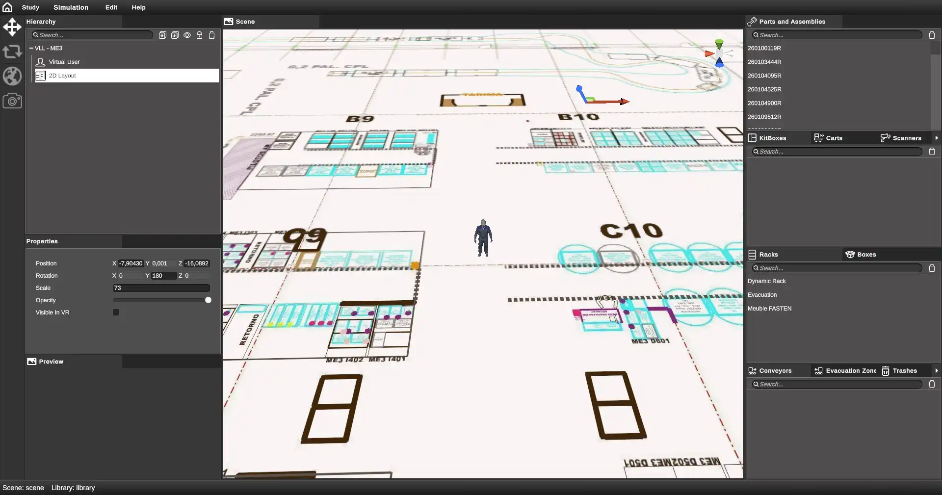
To add a layout to the scene, right-click in the hierarchy tree and choose "Import 2D layout".
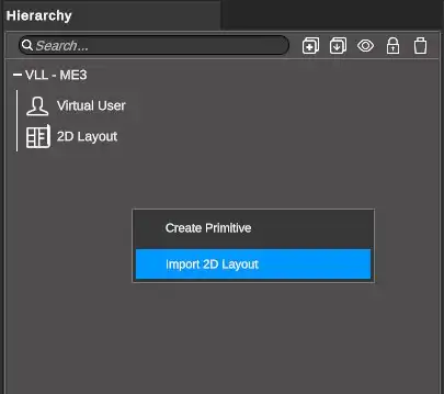
The user is asked to choose an image. An item is then added to the root of the hierarchy tree: it is called 2D Layout.
The layout should then appear as a small entity in the centre of the scene.
You must now set the object to suit your needs.
- Select the item in the hierarchy tree
- Modify the parameters in the Properties window
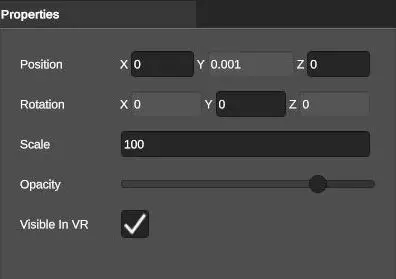
- Position: allows you to specify the coordinates of plane center
- Rotation: Allows you to orient the plane in an orientation around the Y axis
- Scale: scale the plane
- Opacity: global transparency of the plane
- Visible in VR: determines whether the plane is visible or not in simulation
To remove a plane from the scene, select the plane in the hierarchy tree or the 3D scene and, in the hierarchy tree, right-click then remove. It is also possible to use the supp key on the keyboard.
Structural elements
A structural element is a simple primitive, a rectangular parallelepiped, which allows you to represent a different element of the kitting area, which is generally a layout constraint: for example, a pole.
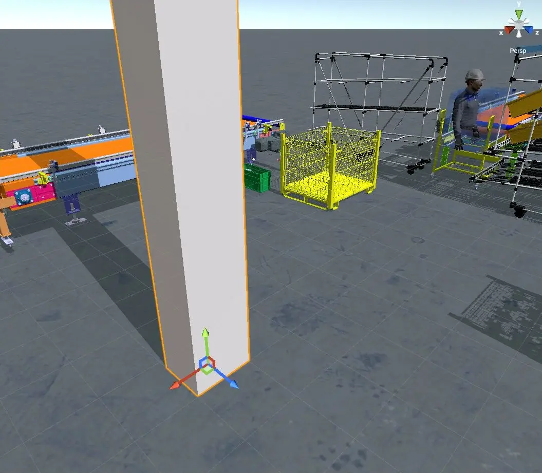
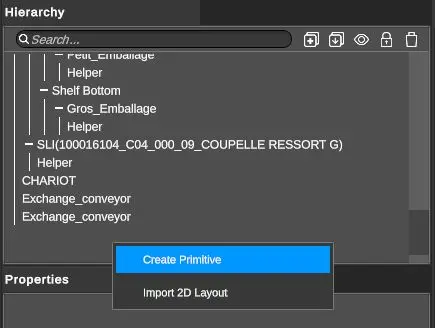
To add a structural element to the scene, right-click in the hierarchy tree and choose "Create Primitive".
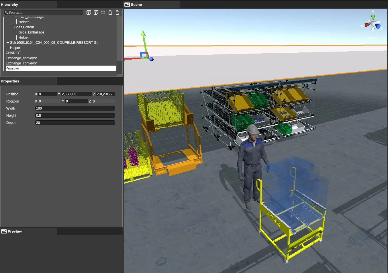
A new element called Primitive is created at the root of the scene and a cube with a 1 metre edge is created in the center of the scene.
To edit the parameters of this primitive, select it in the hierarchy tree or in the 3D scene and modify the following parameters in the Properties window:
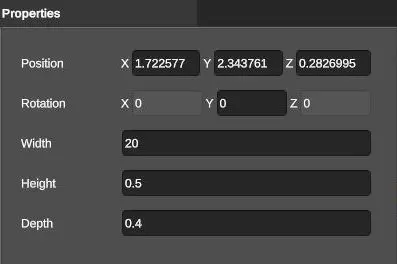
- Position: allows you to specify the coordinates of primitive center
- Rotation: allows you to orient the primitive around the Y axis
- Width, Height and Depth: dimensions in meters
A primitive can be positioned in height to represent horizontal constraints such as a beam or a high conveyor:
Racks and Enhancers
To instantiate a rack or an enhancer, the user must drag and drop an element from the library concerned to the root of the scene in the hierarchy tree: a rack or an enhancer can only be placed directly on the floor.
The element created in the tree automatically contains children: these are the shelves. These shelves can be fitted with packaging (see below).
The properties of a rack or an enhancer are reduced to the position and orientation, but not only:
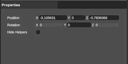
An option has been added to hide the "Hide Helpers" decision aids, useful for pallet racks (storage shelves).
Note
Do not forget that to manually move or orientate a set of furniture, you can make a multiple selection in the hierarchy tree and use the tools in the toolbar!
Packages
On the floor
To create an SLI floor package, drag and drop a package from the library to the root of the decision tree.
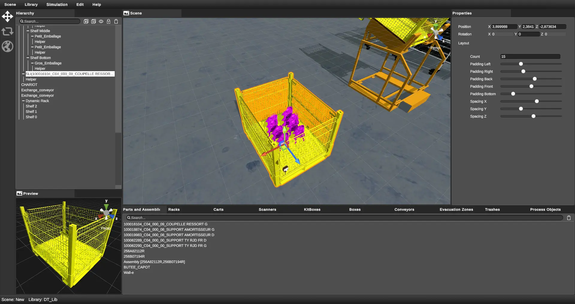
In the Properties window, a ground package has two additional parameters compared to a package in a gravity box: position and orientation.
The position and orientation of a package can also be changed using the tools in the toolbar.
Note
Remember that: to manually move or orientate a set of packages on the floor, you can make a multiple selection in the hierarchy tree and use the tools in the toolbar!
In a rack
To instantiate a package in a rack, drag and drop a package from the library to one of the child shelves of a rack. You can add packages to a shelf as long as there is space left. If there is not enough space left, an automatic rotation of the box will be performed if this allows the box to be inserted. Otherwise, a message appears next to the cursor indicating that there is not enough space "Not enough space":
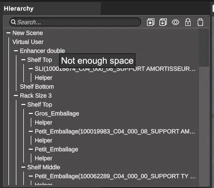
In order to adjust the gap between the packages of a shelf, the shelf type items (directly children of a gravity or a enhancer) have a dedicated property in the Properties window:
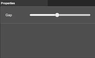
The gap is adjustable and allows you to set the gaps between packages on the same shelf.
You can move one or more boxes from one rack to another. To do this, select the boxes in the hierarchy while holding down the Ctrl key. Then click and drag to the destination shelf.
It is also possible to move one or more boxes from a rack to the floor and vice versa. To do this, select the boxes, then move them to an empty area of the hierarchy.
Other packaging properties
Floor or shelf packs have other properties which are visible in the Properties window. These properties are described in the Parts section as they relate to the arrangement of parts in a package.
Decision Support (Pick To Light)
When a package is instantiated, whether on the floor or on a shelf, a child is automatically added to it: the Helper.
This element represents the decision aid and can itself be selected to modify its parameters:
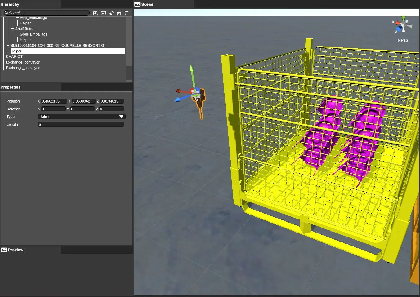
It is then possible to modify the position and orientation of the decision aid by using the tools in the toolbar or by modifying its parameters:
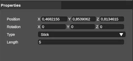
- Position and orientation
- Helper Type: allows you to choose the decision support model
- Length: in the case of a Stick type decision aid, allows you to define the length of the spring
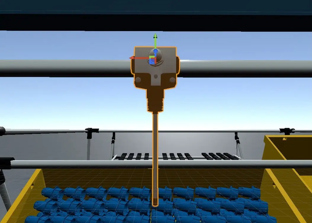
Here is a Stick type decision aid:
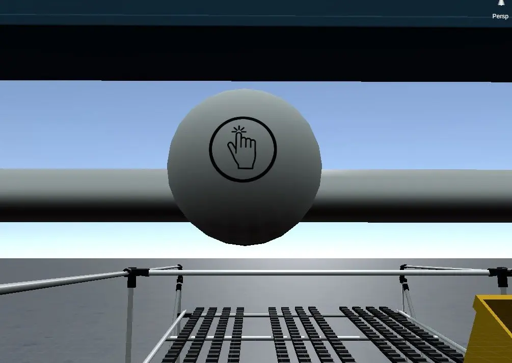
Here is the same object, but this time of type Button:
The parts
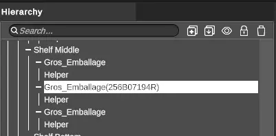
To associate a part reference with a package, drag and drop a part or part assembly (see below) from the library to a package in the hierarchy tree.
When the instantiation is done, the reference of the dragged part appears in brackets next to the package concerned.
The number of parts in the package and the way in which they are distributed is managed in the properties of the package itself (Properties window). The following paragraph describes this setting.
To separate a part reference from a package, select the package in the hierarchy tree or the 3D view, and right click to then select “Unassign Part” in the contextual menu.
Parts layout in the packaging
To edit the parts layout in a package, select the package in the hierarchy tree or the 3D view and adjust the parameters above in the sub window Properties.
In the current version of the software, parts are distributed according to a regular 3D grid.
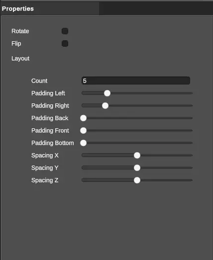
- Count : number of parts in the package
- Padding : allows to define the space between the package borders and the 3D grid of the parts.
- Spacing : define the space between the parts
- Rotate/Flip : allows to rotate 90° the package. The package can turn only if it has enough room to do so in case of racks or enhancers’ shelves.
Note
Padding is used to reposition elements in boxes (by adding margins on sides). Padding is available in the case of imported 3D boxes, but NOT for boxes created with the editor.
Parts assemblies
XR Kitting allows to define parts assemblies, and assemblies of assemblies. This solves the job constraint where the operator has to assembly a set of parts coming from various packages before putting all of it in a kitbox.
Creation
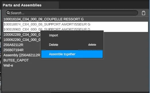
Assemblies are elements from the same library than the parts.
To create a new assembly, select two elements maximum from the library by using the multiple selection (press key ctrl or shift). These two elements can be:
- two parts
- two assemblies
- a part and an assembly
Then by right clicking, select "Assemble together" in the contextual menu.
A new element appears in the library. Its name is Assembly and shows in brackets the two elements of the assembly.
The name of this new element can be modified via the Properties window (field Reference).
At this step, the assembly is defined in terms of reference of assemblies’ parts, but the manner whose parts are assembled (geometrical sense of the term) must still be precise. To do so, edit the assembly.
Edition
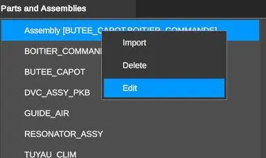
To call the assembly editor, first select the assembly, then right click to choose Edit in the contextual menu.
The main window of the application is completely replaced by the assembly’s editor.
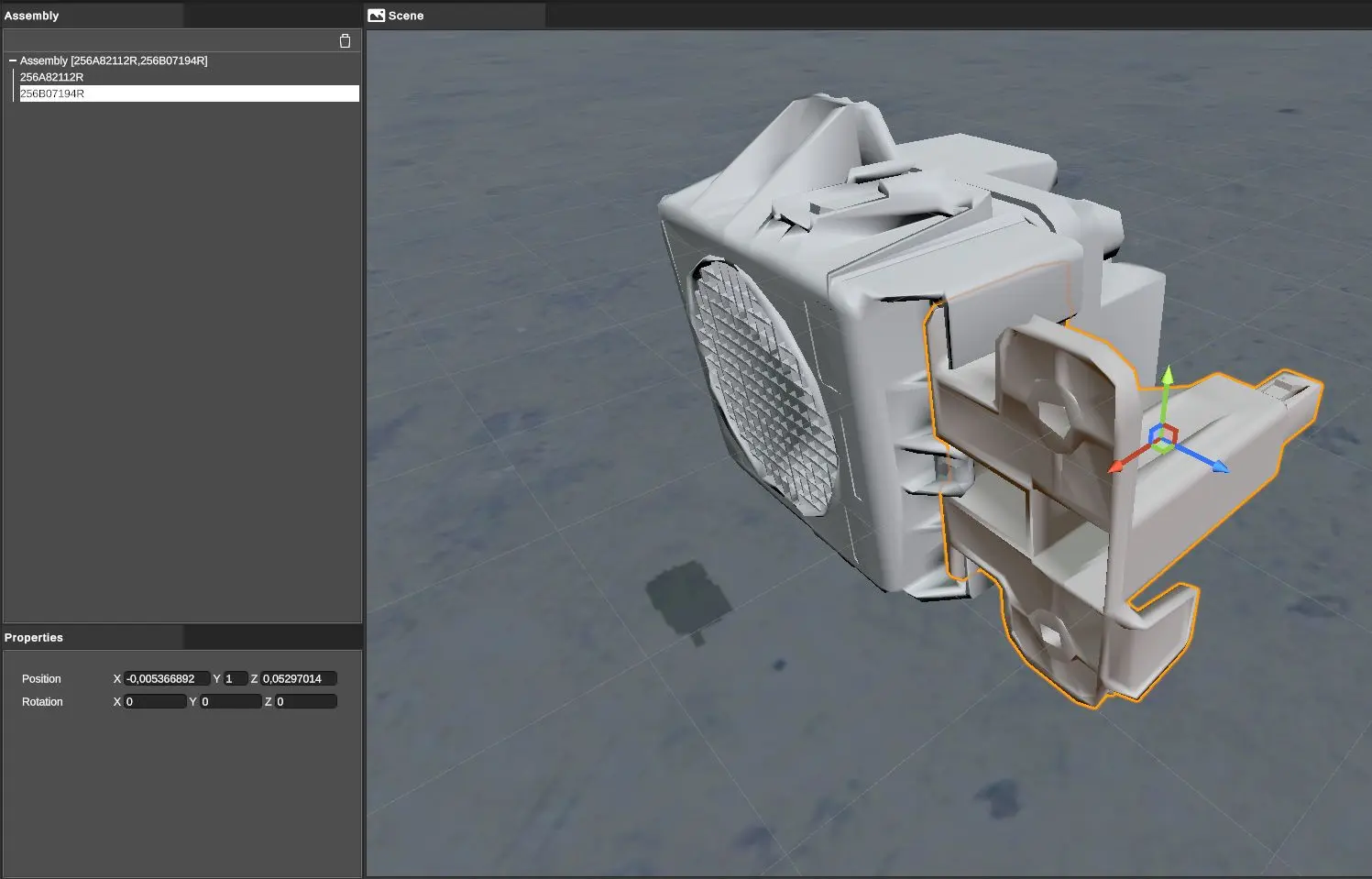
In this editor, it is possible to define the position of a part according to other elements in the assembly. An assembly is the layout of two entities (parts or assemblies), two elements appeared in the hierarchy tree of the editor, and the user define the position and orientation of these elements.
To define these properties, two choices:
- use tools from the toolbar,
- use the fields from the Properties window
In the 3D part of this editor, the POV can be change like in the overall 3D view of XR Kitting.
When the assembly is defined, click on Back (in the upper left corner) to come back to the main window.
Note
In the main view of the application, the operator can visualize the result of the assembly by simply selecting the assembly in the library: the assembly appear in the Preview window.
Several parts Assembly
Do not forget an assembly can be itself an assembly of assemblies. It is this hierarchy of elements that let to create several parts ‘assemblies. But a certain order must be respected.
Take the example of 3 parts A, B, and C that were assemblies like this:
-
A+B = AB Assembly
-
AB+C = ABC Assembly
In simulation, the operator should first assemble A and B, and then from this assembly, assemble C.
The manual carts
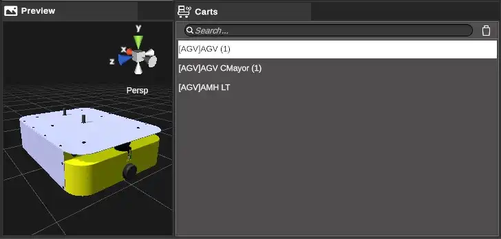
Manual carts and AGV are presents in the same library named Carts.
To import a 3D model, like in all other libraries (but Racks), use the right click. In this case precisely, choose Import Cart for the manual cart.
A manual cart is distinguished from AGV in the items list by the prefix [MAN].
The current version of the software can manage only one cart in the scene.
AGV
AGV are presents in the same library than manual carts (Library named Carts.
An AGV is distinguished from a manual cart in the items list by the prefix [AGV].
AGV Properties
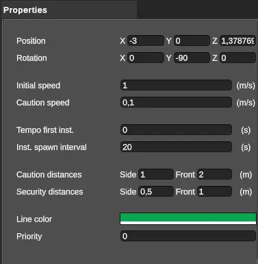
- Position: the AGV position in the world
- Rotation: AGV rotation
- Initial speed: AGV initial speed
- Caution speed: Speed when one element enters the AGV caution zone
- Tempo first inst.: temporization before the launch of the first AGV
- Inst. spawn interval: interval between the appearance of the AGV various bodies
- Caution distances: size of the caution zone
- Security distances: size of the security zone
- Line Color: color of the trajectory
- Priority: The AGV priority according to the others AGV in the scene
Trajectories edition
AGV trajectory is a notion defined at the scene level and not at the library level. Right, the same AGV 3D model can be used in several different kitting zones, but there will be a different trajectory for each case.
To edit a trajectory, first instantiate one AGV in the scene by dragging and dropping the AGV item from the library to the hierarchy tree.
Then select the AGV instance, and thanks to the right click, choose Edit Trajectory in the contextual menu:
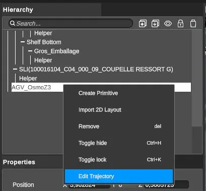
This action leads to the opening of the AGV trajectories’ editor, that replace the main window of the application, like the assembly editor’s case (see above).
Trajectories editor
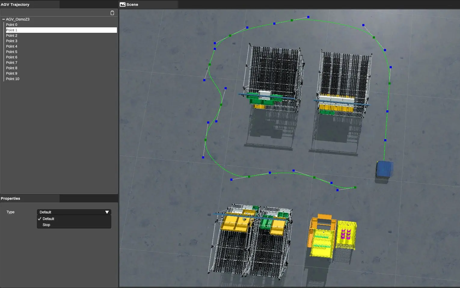
We highly recommend position the camera in top view for the edition of trajectories. The POV can be modified as wanted with the same buttons on the mouse and tool in the upper right corner than the case of the main 3D window of the application.
At the beginning, the AGV trajectory is a straight line defined by two points.
Two types of points on the trajectory:
- Trajectory’s points in green: it is a path constraint
- Control points for tangents: these points are used to define tangents at the trajectory’s points (to define the curve)
Move a trajectory point
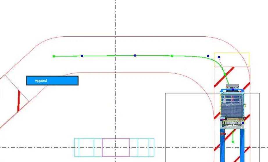
To add a point, right-click on the floor at the location of the addition and choose Append.
An added point with this method is always add at the end of the trajectory.
Move a trajectory point
To move a trajectory point (green), left click on it and move it by holding the button.
If you have inserted several AGVs in your scene, when you move a trajectory point of your AGV, this point will be automatically snapped to a trajectory close to another AGV if you approach this point of this trajectory.
Insert a trajectory point
To insert an intermediate point on an existing trajectory, simply position yourself at the desired location and right click to choose Insert:
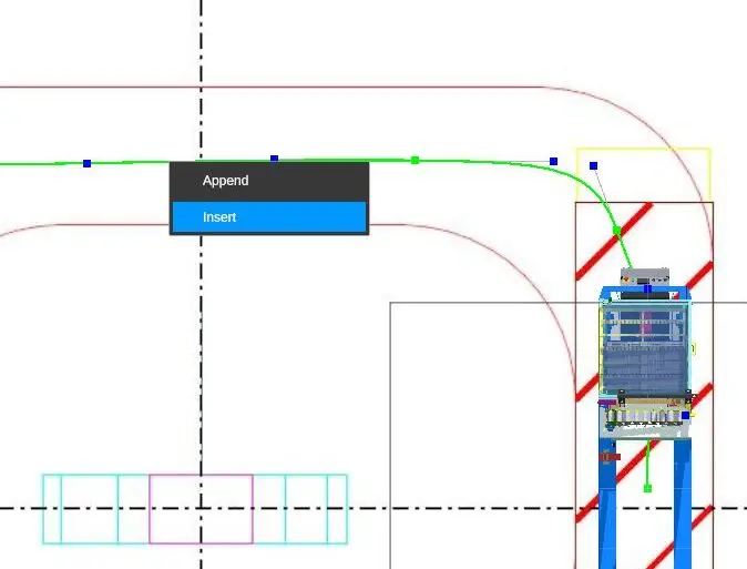
Delete a trajectory point
To delete a trajectory point, simply right-click on the point and choose Remove.
Editing tangents
Tangents are used to define incoming and outgoing curvature constraints on a trajectory point.
The tangent points (blue dots) can be positioned by left clicking on them and moving the mouse while holding the button.
When defining a tangent, the orientation and length of the tangent influence the curvature.
When the trajectory is defined, simply press Back at the top left to return to the main application window. You can, of course, return to editing the trajectory at any time.
Insert a STOP point
A new Stop button allows you to stop an AGV on a trajectory point. A Start button will be added to allow the AGV to be restarted manually.
To add a Stop point: select a path point and in the properties window, select the "Stop" type.
In the 3D scene, a child of the AGV is added in the hierarchy. This is the Stop point which can be positioned in 3D space manually as desired.
Insert a timeout point
A new timer button allows an AGV to be stopped at a trajectory point for a given period of time.
The AGV will automatically restart after a manually defined period in seconds.
To add a timeout point: select a trajectory point and in the properties window, select the "Tempo" type.
To define the duration of the timeout point, modify the value of the "Time" field that was added automatically. This time is expressed in seconds.
Editing the speed of an AGV
It is possible to modify the speed of the AGV at each point of its trajectory. The speed defined at this point will then be applied until a new speed is defined.
To modify the speed of an AGV: select a point of its trajectory and in the properties window, select the "SpeedModifier" type. Then in the "Speed" field define a speed in m/s.
Modify the colour of the trajectory
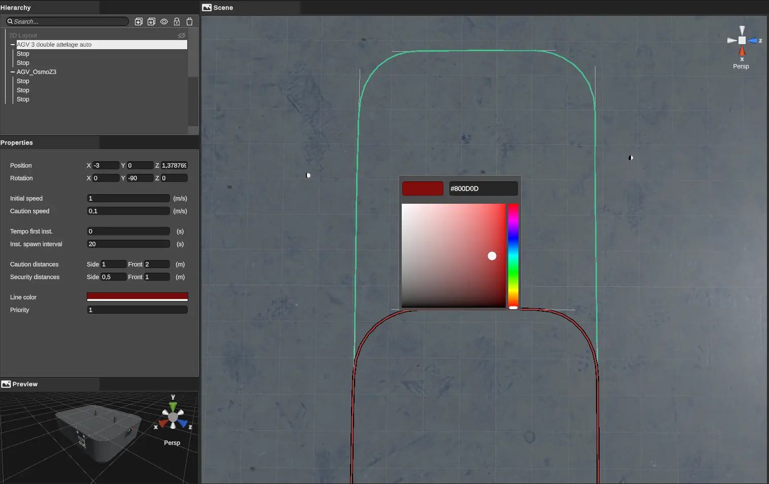
When using several AGVs in a scene, the trajectories can be brought to cross each other. To facilitate reading and editing, each AGV trajectory has its own colour, defined automatically when the AGV is created.
It is possible to customise this colour by selecting the AGV in the scene and then, in its Priorities window, click on "Line color" and use the color-picker to modify the colour of the trajectory. It is also possible to insert a hexa-decimal code in the dedicated field of the color-picker.
Activate le kit
It is possible to modify the trajectory point that will activate the current kit: start the time tracking, activate the decision aids...
To do this: click on a trajectory point, then in the "Properties" window check the "Enable kits" box.
AGV position
The position of the AGV in the 3D view of the main window of the application directly defines the position of the starting point of the trajectory. If you move the AGV using the translation tool in the toolbar or the numerical editor (Properties window), you move the entire path with it.
Intersection between several AGVs
It is now possible to add several AGVs in the same scene. To avoid collisions between these AGVs, it is possible to define simple rules.
Priority
The priority parameter allows you to give priority to an AGV when it crosses another one. The AGV with the highest priority will pass. The AGV with the lowest priority will stop.
A default priority is set when adding an AGV to the scene.
You can edit this priority by selecting the AGV in the scene, then in the Properties panel, change the value of the "Priority" field.
It is not possible to define the same priority for several AGVs.
Caution and Safety area
It is possible to go into more detail in the management of intersections by using two detection zones around the AGV.
The "Caution zone" allows the speed of the AGV to be modified when an obstacle enters this area.
"Security zone" allows the AGV to stop completely when an obstacle enters this area.
The size of these areas by default is :
-
"Caution Zone": 1m on the sides of the AGV, 2m at the front of the AGV
-
"Security Zone": 50cm on the sides, 1m in front.
You can change the size of these areas by selecting the AGV in the zone, then in the properties window, change the values for "Caution distances" and "Security distances".
It is possible to "disable" these aeras by entering distances of 0m. The highest priority AGV will then pass through the lower priority AGVs. It will not, however, pass through the player or the set.
MGV
A MGV is a path-guided manual cart. MGVs are distinguished from other carts in their library by a [MGV] prefix.
MGV properties
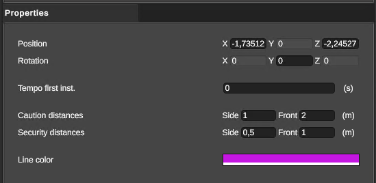
- Position: MGV position in the world
- Rotation : rotation of the MGV
- Tempo first inst. : delay before the first MGV is launched
- Caution distances: size of caution zone
- Security distances: size of security zone
- Line Color: trajectory color
Path editing
MGV trajectory editing is identical to that of the AGV. Please refer to the previous paragraph.
Activate kit
It is possible to modify the trajectory point that will activate the current kit: start time tracking, activate decision aids, etc.
To do this, click on a trajectory point, then in the "Properties" window, check the "Enable kits" box.
Prekits and prepicks
Two new types of packaging have been added since version 2.1.6. Like conventional packages, prepicks and prekits are instantiated on a gravitational unit, so that they can be manipulated in simulation. There is one difference, however:
-
Prepick: prekit parts can be picked individually.
-
Prekit: the complete prekit can only be manipulated.
Position parts in prekit
To edit the positions of prekit parts, select the prekit in the library, then right-click and select Edit from the context menu. The prekit editor then appears, replacing the main application window:
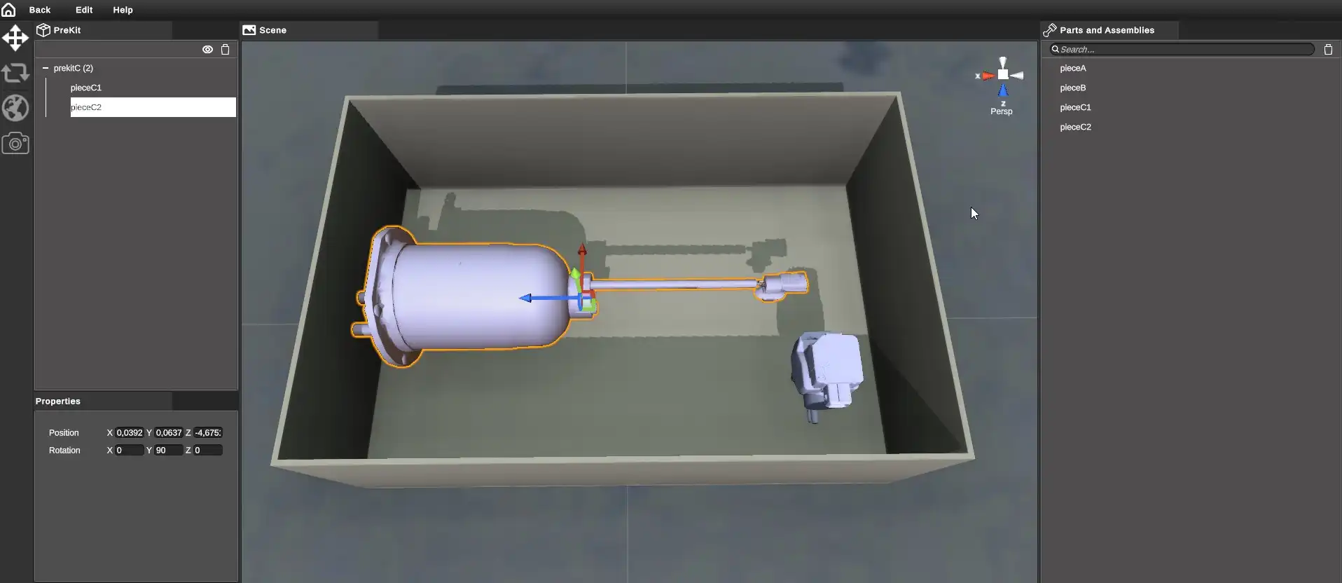
Parts and assemblies from the Parts library appear on the right.
To edit the positioning of a part, first drag and drop it from the library on the right into the design tree, as a child of the prekit.
The position and orientation of the part can then be defined using the tools on the toolbar or from the numerical fields in the Properties window.
By default, all parts added to the prekit will be visible, but you can choose to show/hide (in the editor only) one or more parts from the hierarchy on the left:
-
right-click on the part, choosing the "Toggle hide" option.
-
by selecting one or more parts, then using the Ctrl+H keyboard shortcut.
-
by selecting one or more parts and then clicking on the eye in the topbar to the left of the wastebasket.
Once the positions have been set, simply click on Back in the top left-hand corner to return to the application's main window.
Create prepick zones
In the case of prepicks, parts can be grouped into zones. In the prepick editor, you can add different parts to each prepick zone. In simulation, only one part is instantiated in each prepick zone.
To create zones in a prepick, select the prepick in the library, then right-click on Edit in the context menu to open the prepick editor. By default, each new prepick has one zone.
You can create a new zone by clicking on the "+" icon in the top menu.

It is also possible to duplicate an existing zone with its children using the keyboard shortcut Ctrl+Shift+D. In this way, you can create the various zones of your prepick and then drag the desired parts or assemblies from the library on the right into the editor tree on the left.
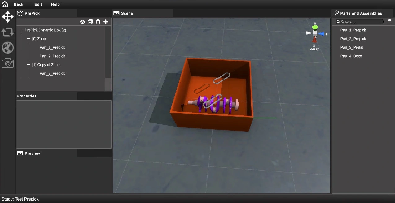
The KITBoxes
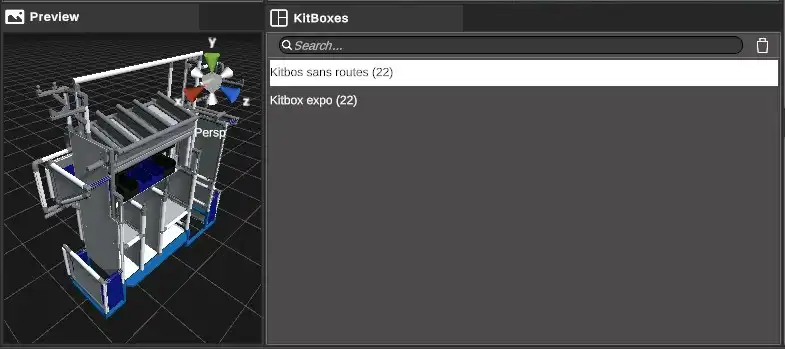
To import a kitbox, right click in the Kitboxes library and choose Import.
Editing the position of a Kitbox on a cart
Case of the manual cart
In the case of manual cart, we define the position that the kitbox will have on the manual cart when it is loaded from a conveyor.
This notion is a library notion and not a scene notion. This allows to prepare kitbox-cart relationships once and for all and to be able to use them in various kitting scenes.
To define this position, select the manual cart in the library and choose Edit from the context menu that appears with the right button.
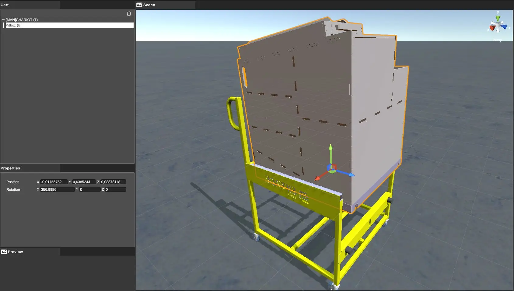
The kitbox position editor appears and replaces the main window of the application.
To set the kitbox position, first drag and drop the desired kitbox under the cart in the hierarchy tree of this editor.
The position and orientation of the kitbox can then be set using the tools in the toolbar or the digital fields in the Properties window.
This operation can be repeated for all Kitboxes to be defined.
When editing is complete, simply click on Back at the top left to return to the main window of the application.
The kitboxes thus defined in position and orientation appear in ghost rendering in the main view of the application:
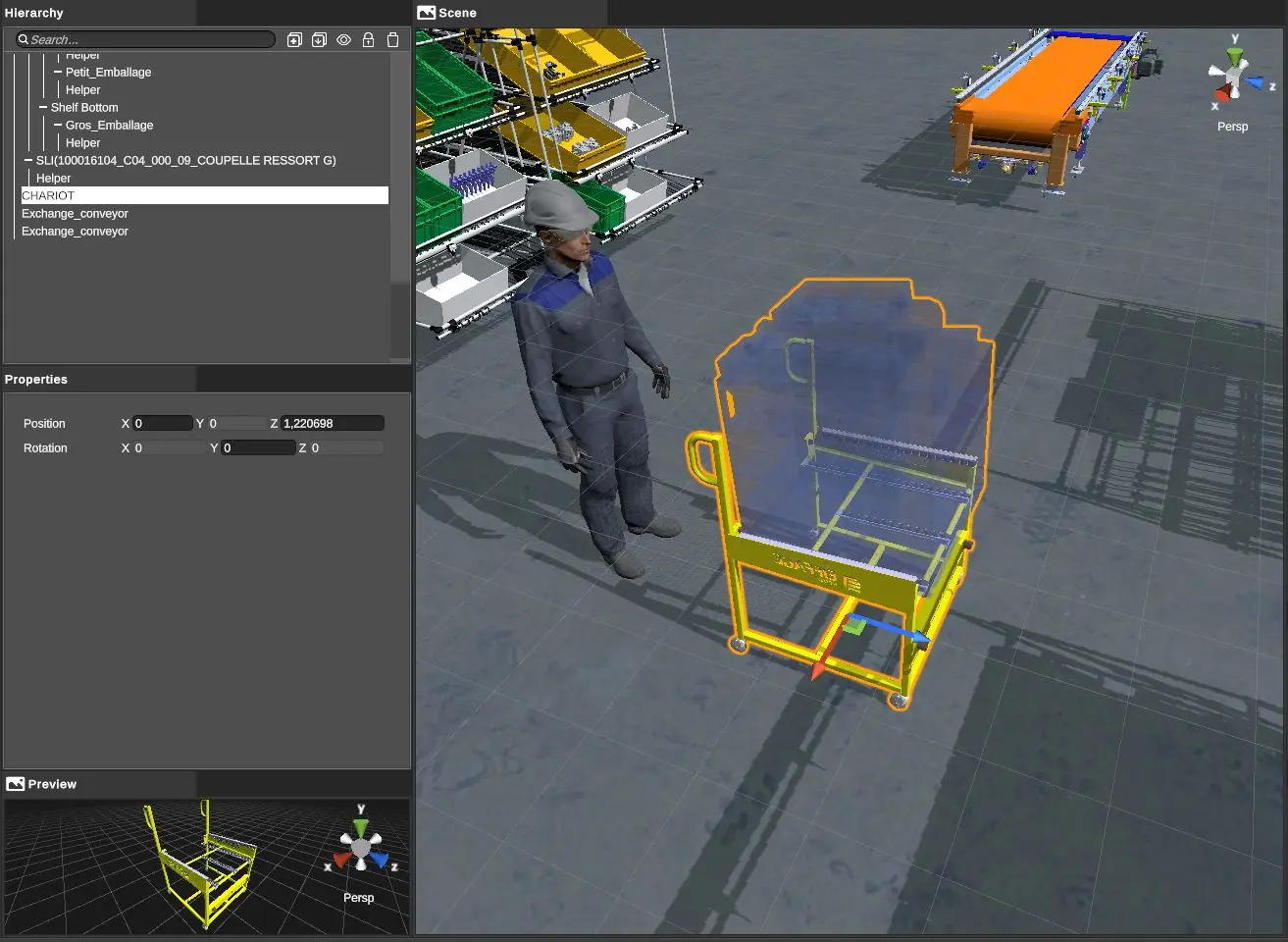
The AGV's case
Editing the position of a kitbox in relation to an AGV is done in the same way as in the case of the manual cart (see above).
Editing the position of parts on a Kitbox
This notion is also a library notion.
It is a job that requires a lot of manipulation since it is a question of defining the location and orientation of each part or each assembly of parts that will come in the kitbox.
Once this editing is done, it will be saved with the library and can then be used in various kitting scenes without having to go back to it.
To edit the positions of parts in relation to a kitbox, select the kitbox in the library and then right click on Edit in the contextual menu.
The kitbox editor then appears, replacing the main window of the application:
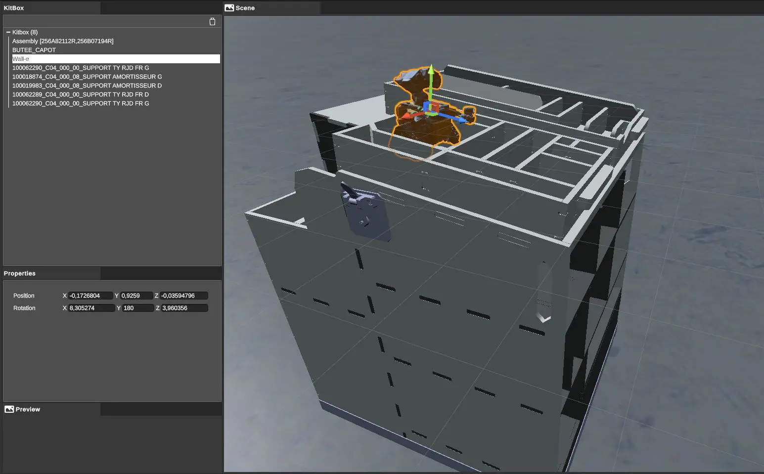
The parts and assemblies in the Parts library appear on the right. Since version 2.0.5, it is also possible to add prekits to a kitbox. The dedicated prekit library is thus also displayed on the right panel.
To edit the positioning of a part, first drag and drop it from the library on the right to the hierarchy tree, as a child of the kitbox.
The position and orientation of the part can then be defined using the tools in the toolbar or from the numerical fields in the Properties window.
By default, all parts added to the kitbox editor will be visible, but you can choose to show/hide (in the editor only) one or more parts from the hierarchy on the left:
-
right-click on the part, choose the "Toggle hide" option.
-
by selecting one or more parts, then using the Ctrl+H keyboard shortcut.
-
by selecting one or more parts and then clicking on the eye icon in the topbar on the left of the trashcan icon.
Once you have set up the positions, simply click on Back in the top left corner to return to the main window of the application.
The Kitboxes conveyors
The conveyors are located in the Conveyors library:
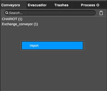
The same 3D model of a conveyor can be used in both directions: one instance of the conveyor will be defined as a load and the other as an Unload for example.
Here are the properties of a conveyor instance in the scene (after instantiation by drag and drop in the hierarchy tree):
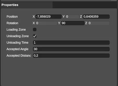
- Loading Zone : allows to define the conveyor in the loading direction of a kitbox on a cart
- Unloading Zone : allows to define the conveyor in the unloading direction
- Load time : time in seconds of pause in the simulation to simulate the handling time during loading or unloading (impact on cycle times)
Triggering loading/unloading
A conveyor triggers the loading or unloading of a kitbox on detection of the proximity of a cart. To define the detection zone of the conveyor, select the conveyor in the library, then right click and choose Edit in the contextual menu:
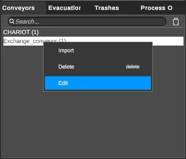
This action opens the Conveyor Editor, which replaces the main application window.
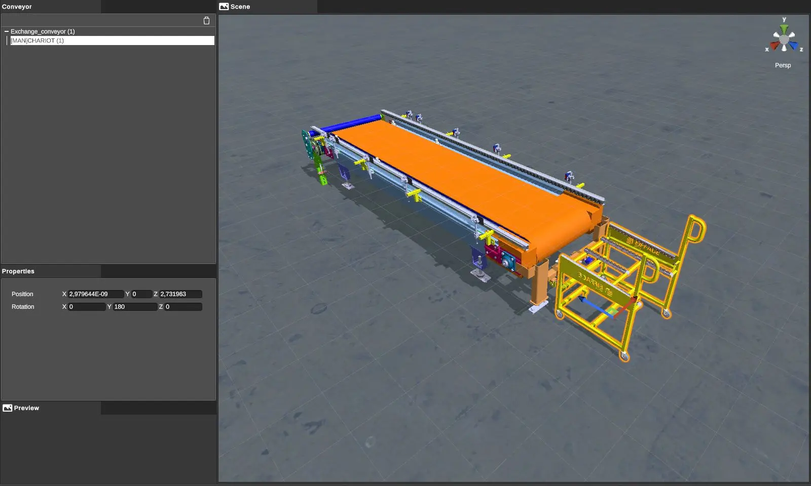
This tool allows you to place the cart in relation to the conveyor to define the position and orientation that the cart should have to trigger a loading or unloading.
To place the cart, you can use the tools in the toolbar or the digital fields in the Properties window.
Once you have placed the cart, simply click on Back in the top left-hand corner to return to the main window.
Once in simulation (see Simulation), a kitbox loading or unloading will be triggered when the manual cart is approximately placed according to the position and orientation defined in the editor.
Packages evacuation areas
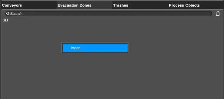
Furniture used as an evacuation zone for packages is located in the Evacuation Zones library.
To import such a furniture, right-click in the library and choose Import. .
For a package to be detected by an evacuation furniture, the package must be set up as a package to be evacuated, not as a package to be discarded.
To set up a package to be disposed of - it must be set as such in the Library:
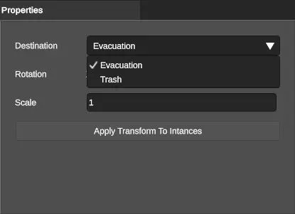
Once the packaging has been selected in its library, in the Properties window, you must choose "Evacuation" as the Destination mode. Packages set this way will be evacuated when they touch the furniture during the simulation.
The trashes
A package can be set up for an evacuation zone or a waste trash.
In order for a package to be disposable in a trash, it must therefore be set up as follows:
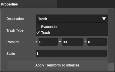
When the "Trash" mode is selected, an additional property appears:
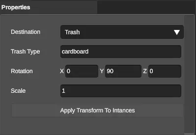
This is the Trash Type. This text field allows you to choose a type of trash. The user can create as many types of trashes as necessary since this field is free. Here the implementer has chosen a "cardboard" type.
It is now necessary that at least one trash in the scene is of type "cardboard" since it is the type which has just been defined.
To do this, select in the hierarchy tree an instantiated trash, and in the Properties window enter the corresponding type:
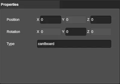
We have chosen to set the trash type parameter at the hierarchy tree level and not at the library level to allow you to use the same library element several times but with different types.