![]()
Cables 
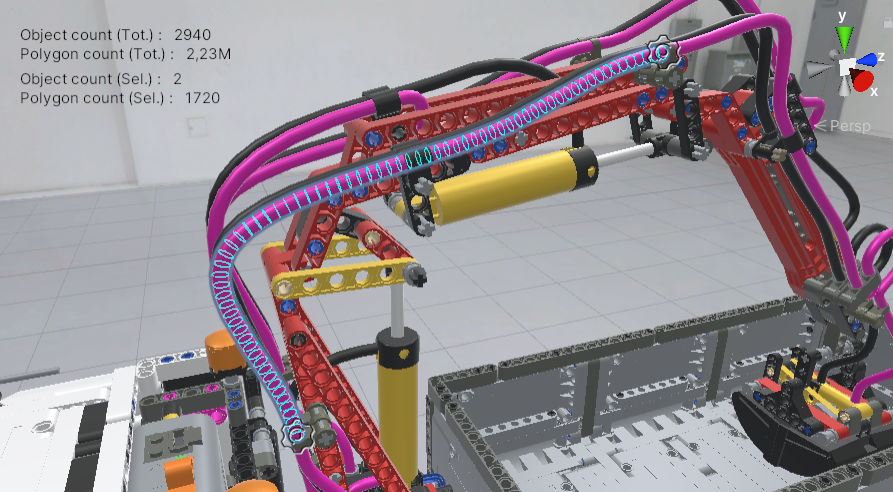
INTERACT can help you to simulate cables by using physical properties. We use a beam finite element model to process flexible cables.
Tutorial
Check the interactive tutorial on cables to discover cable features. Tutorials > Show Tutorials > Cables.
There are two ways of generating a cable:
- from a CAD model
- from a spline
When your cable is generated, you can customize its shape, length, position, radius and more.
Create a Spline 
If the cable geometry is not yet available in your product design, you might consider using INTERACT to help you define your cable routing.
To do so:
- Use the toolbar menu GameObject > Spline > Draw Splines Tools
- Define your knots by clicking in the scene view
- Press Esc when done
For more information about how to create a Spline and manipulate it, click here.
Spline doesn't appear
If you created a Spline, and the Spline object appears in the hierarchy but not in the scene view, you probably unchecked the toggle visibility of all Gizmos in the Scene view.
In the top right corner, activate the visibility by clicking this icon. 
Physics
At this step you have only created a spline with no physics behaviour. To simulate the bending of your spline, check the following create cable section.
Create Cable
To apply physics to your cable geometry, whether it comes from CAD or a spline:
- Select the cable geometry in the Hierarchy tab or Scene view.
-
Click on INTERACT > Physics > Cable > Create Cable...


Selected objects
If you select one or more objects when creating one or more cables, they are automatically added below Game Objects > Selected Object(s), but you can still edit them by deleting an object or adding one in the Selected Object(s) list.
-
Configure your cable (note that all properties (except Radius) can be edited after):
- Number of nodes per meter: The resolution used by our finite element method to compute the physics of the cable.
- Radius (m) (for the Splines only): cable radius in meters.
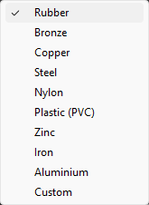
- Material: You can use presets to configure the physical properties of your material. Drop-down and select your material.
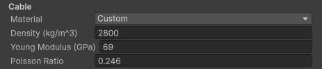
- Density, Young modulus and Poisson ratio are physical properties commonly found for a material. Units are measured using the International System of Units. These properties can be changed when using Custom as Material.
- Preformed cable.
-
Click Create.
-
A Cable node is added as child of the selected node in the Hierarchy tab and a Cable Generator component is added in the Inspector tab.
Geometry
To recognize shapes for a cable's parameters, you need to use either an open deformed cylinder or a closed surface. Tessellation should be quite detailed in order to perform well.
Cable properties
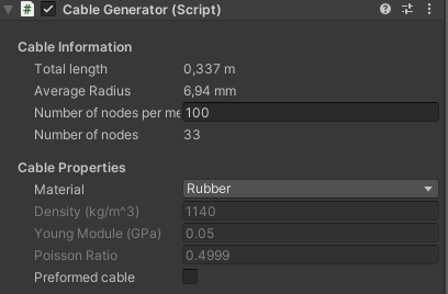
The cable resolution (nodes per meter) and its Material properties can still be edited after its creation in the Cable Generator component.
You can select the Cable GameObject, which is a child of the spline or CAD model that the cable has been generated from. Its XdeCircularBeam component contains all the information relating to the cable's physical material and simulation properties.

- Collision Group: Like any physicalized object, you can define a Collision Group for your cable to make it collide with other objects.
- Beam info section: Cable radius (in mm) and total length (in m). The average segment length (in m) is the length between two nodes.
- Number of Nodes (to the right of Reference or Initial Configuration): Number of nodes used by our FEM to compute the physics of the cable.
- Attach Points section: When your cable is created, it only has StartAttachPoint and EndAttachPoints, but any new Attach Point will appear here.
Edit the cable
Cables generated from a CAD model or a spline have a Spline Container. This enables you to lengthen, shorten, or move your cable.

-
Select the GameObject you generated a cable from (the one with the Spline Container in its components).
-
Select the Move tool, then the Spline icon in Unity's Tool Settings Overlay as shown in the picture.
- Select the knot you want to move and move it.
-
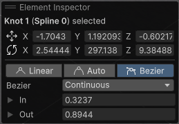
You can toggle knot type in Unity's Element inspector. Learn more about splines manipulations.
Knot
When you create the spline, you add knots by clicking on the view scene in order to place points. When you create it from a CAD model, the knots are automatically added based on the curvature.
Preformed Cable
In order to compute a cable's deformation, we need to set up two states:
- The initial configuration, which is the initial starting position of each point in the cable.
- The reference configuration, which is the position with no internal stress on the cable. For a straight cable, initial and reference positions are the same.
The Preformed cable property allows users to set the reference configuration:
You will find Preformed cable property both in Create cable window and Cable Generator component which allows you to change this option after creation.
- If Preformed cable is unchecked, the reference configuration of the cable is a straight line. If the current shape of the cable is not straight, it means this cable is already affected by internal forces. When playing your simulation, if the cable is not attached, it will try to take the straight position.
- If Preformed cable is checked, initial positions and reference positions are the same. So when playing the simulation, its reference shape will be the one you gave it in Editor mode. Use this for beams or cables that have been built with a specific shape.
Example
Consider two identical cables, with the left one being "preformed" and the right one not.
For both cables:
- From the Hierarchy tab, expand Spline > Cable > CableEndAttach and select it (in this example, it is located at the bottom of the cables).
- From the Inspector, in the Xde Weldable Joint component, uncheck Weld At Start.
- Play the simulation.
Notice the following:
- The left one is affected by gravity but keeps its initial shape (following the points 1,2,3,4,5).
- The right one is also affected by gravity but is become a straight line (the upper curvature depends on CableStartAttach's position).
