
Scenarization
An assembly sequence is the order in which parts are put together to form a complete product, broken down into a series of steps. INTERACT lets you build these sequences and visualize how the parts fit together, so you can check that the product is assembled correctly and efficiently. Assembly sequences can also be used as the basis for a training application.
Within INTERACT, you can create assembly sequences using the Scenario Graph.
Create a Scenario
Here are the key steps to create a Scenario in your Unity Editor with INTERACT:
-
Create a scenario, in the INTERACT menu: INTERACT > Scenarize > Create scenario.
This creates a [Scenario] game object in the hierarchy window. -
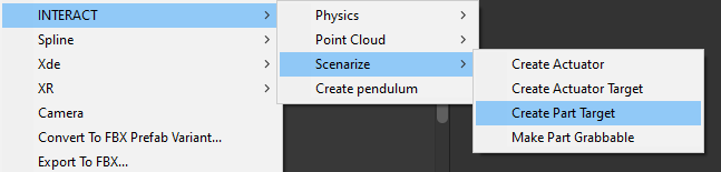
To make the object accessible from your scenario, it needs an XdeAsbPart component. If it is physicalized, it already has one. Otherwise, right-click on the object in the hierarchy and go to INTERACT > Scenarize > Make part grabbable. This also makes it grabbable in VR.
-
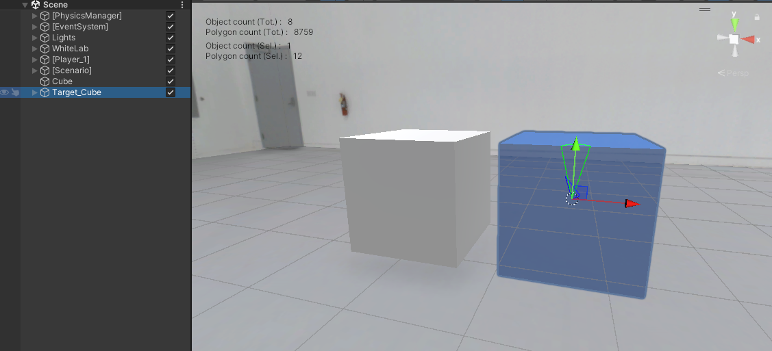
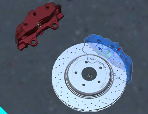
Indicate the target of this object: click on INTERACT > Scenarize > Create Part Target. The target is created, it has the appearance of a blue ghost.
-
Place this target where the part should go.
-
This creates a Placing Step in your [Scenario] with the corresponding part to place and target.
-
To have an overview of the steps, go to: INTERACT > Scenarize > Show scenario graph.
- You will now be able to connect the steps to make sequences (ex: the assembly of a wheel starts only if the brake disk is in place AND the bolts have been screwed).
- You can also give specific names to your Steps.
- Go to Customize scenario to learn more.
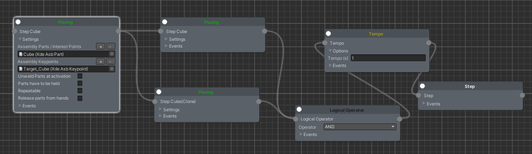
The Scenario manager automatically handles the visual helpers in runtime (trajectories, ghost, instruction panel). In Simulation (when you switch to the PLAY mode), the transition between steps is done when the part to place reaches its target.
Edit the Target
The XdeAsbKeypoint has three roles in the assembly workflow:
- Trigger: it starts a step once a condition is met — either the part approaches a Keypoint Transform, or a Joint State nears its target position.
- Snapping: it adjusts the part's position and rotation so it aligns precisely with the target.
- Welding: it lets the part be welded to another object, completing the assembly.
Keypoint Transform
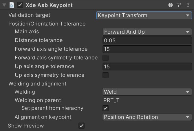
When using the Keypoint Transform validation target mode, the part to place has to reach the position and rotation of the keypoint.
- Main axis:
You can choose which pair of main axes best fits your target. These axes are expressed in the local frame of your part:
| Main axis | description |
|---|---|
| Up and Right | Y (green) and X (red) |
| Forward and Up | Z (blue) and Y (green) |
| Right and Forward | X (red) and Z (blue) |
Joint State
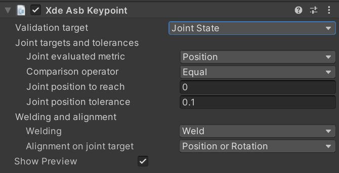
When using the Joint State validation target mode, the joint on the part to place (the one with the XdeAsbPart component) has to reach the target position and/or velocity.
Xde Unit Joint Monitor
A XdeUnitJointMonitor component is required on the part to place in order to use the Joint State validation target mode.
- Joint evaluated metric: Position, Velocity or Position and Velocity
- Comparison operator: Choose whether the Joint evaluated metric has to be Equal, Greater than, Less than or not equal to the Joint position/velocity to reach value
- Joint position/velocity to reach:
float - Joint position/velocity tolerance:
float
Welding and alignment
-
Welding:
Welding description Weld Weld the part to place to the target when keypoint is reached Unweld Unweld the part to place (if already welded to another part) when keypoint is reached None Do nothing -
Set parent from hierarchy: when enabled, the target is welded to its parent GameObject in the hierarchy. Disable this property if you want to choose which rigid body the keypoint is welded to instead.
-
Alignment on keypoint: allows you to set on which keypoint axis the part to place will be aligned to when the validation target is reached :
- Position and Rotation
- Position (see example below)
- Position and Right axis
- Position and Up axis
- Position and Forward axis
- Rotation (see example below)
- Right axis (rotation around X axis)
- Up axis (rotation around Y axis)
- Forward axis (rotation around Z axis)
- None
Examples:
Position: only the part's position is aligned to the target; its rotation is not taken into account:
Rotation: only the part's rotation is aligned to the target; its position is not taken into account (but must still be within the distance tolerance):
- Show Preview: Show or hide the target preview (blue ghost).
Dismountable parts
A part can get welded in place in three ways: through a Placing step's keypoint (see Welding and alignment above), through a script, or through the "weld to void" release behaviour. In all three cases, grasping the part does not free it on its own.
Whether a grasp is allowed to unweld a part is controlled by the Dismountable property of its XdeAsbPart component, which is disabled by default.
- Dismountable enabled: grasping the part automatically unwelds it, so it can be pulled away again.
- Dismountable disabled: grasping the part has no effect on its weld state, it stays fixed in place.
This lets you reuse the same grasp gesture for both mounting and un-mounting a part, without extra scripting: enable Dismountable on parts that a user should be able to remove again (maintenance, disassembly), and leave it disabled on parts that must stay permanently in place once assembled.
If a Placing step is set to Repeatable, its parts will usually also need Dismountable enabled, otherwise the user has no way to physically pull a welded part off the keypoint again to redo the step.