Wire 
The XDE Wire component models a taut cable: a tension-only element suited for cranes, hoists, winches, and pulley-guided systems. Unlike the flexible cable — which uses a beam finite-element model and handles bending and torsion — the Wire is intentionally minimal:
| Behaviour | Wire | Flexible cable |
|---|---|---|
| Tension (traction) | ✅ | ✅ |
| Compression | ❌ | ✅ |
| Bending / torsion | ❌ | ✅ |
| Collision | ❌ | ✅ |
| Dynamic length (winch) | ✅ | ❌ |
This makes the Wire computationally lightweight and well-suited for lifting simulations.
Create a Wire
The INTERACT editor menu INTERACT > Physics provides shortcuts to create wire objects in one click (Wire Attach Point, Wires, Wire winches).
1. Add Wire Attach points
A Wire connects a sequence of passage points, each represented by an XdeWireAttach component.
- Use
INTERACT > Physics > Create Wire Attach Point. - Assign a Rigid Body in the Body field — this is the physicalized object the point is attached to.
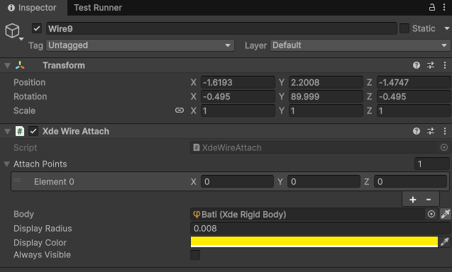
The attachment position is expressed in the local frame of the GameObject. By default it is (0, 0, 0), but you can offset it to place the cable attachment precisely on the body.
A single XdeWireAttach can hold multiple attach points (the Attach Points array). Each entry is an independent position in local space, selectable by index when building the wire path.
Gizmo
Each attach point is represented in the scene view as a sphere. Use Always Visible to keep it visible even when the object is not selected, or adjust the Display Radius and Display Color for clarity.
Repeat this step for every passage point along the cable path (start, intermediate pulleys, end).
2. Define the Wire path
Once your attach points are ready:
- Create Wire connecting them with
INTERACT > Physics > Create Wire. - In the Points array, add one entry per passage point in path order.
Each entry references:
- Attach — the
XdeWireAttachGameObject. - Point Idx — the index within that attach's Attach Points array (usually
0).
Order matters
The wire follows the points in array order. An incorrect sequence will produce wrong cable routing. Use the scene gizmo (a line drawn between all points) to verify the path visually.
Wire parameters
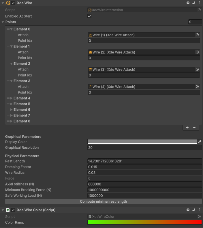
Wire Radius (m)
Visual and physical radius of the cable. Expressed in meters.
Rest Length (m)
The unstressed cable length. It must match the geometric length of the defined path at the moment the simulation starts, otherwise the wire will immediately apply a force.
Compute Minimal Rest Length — click this inspector button to automatically set the rest length to the current drawn path length. This is the recommended approach in most cases.
Axial Stiffness (N)
How much the cable stretches under load. Typical values for a steel cable: 300 000 – 1 000 000 N.
Damping Factor
A numerical damping applied to the wire dynamics. The default value (0.015) is suitable for most lifting scenarios.
Minimum Breaking Force (N)
Force beyond which the cable breaks and fires the onBrokenWire event.
Default is 0
The default value is 0, meaning the cable breaks immediately under any load. Always set this to a realistic value, or to a very large number if breakage is not desired.
Safe Working Load (N)
The maximum recommended operating load, below the breaking force. Used exclusively for visual feedback via the Wire Color component — it has no effect on the physics.
Enabled At Start
When unchecked, the wire is created in a disabled state and must be activated at runtime via SetEnabledAsync.
Wire Color
Add the XDE Wire Color component (on the same GameObject as XDE Wire) to colorize the cable dynamically based on the current tension.
The component maps the current force to a color gradient (the Color Ramp field):
- A normalized value of
0→ no tension → first color in the gradient. - A normalized value of
1→ force equal to Safe Working Load → last color in the gradient. - Values above
1(force exceeds SWL) clamp to the gradient's last color.
Typical setup
Map green → yellow → red across the gradient to give operators immediate visual feedback about load levels.
Requires Safe Working Load
The normalization divides by safeWorkingLoad. If this value is 0, the component will produce a division by zero. Always set a non-zero Safe Working Load when using Wire Color.
Winch mechanism
A winch mechanism is used to dynamically change the cable length at runtime.
The winch ties the rotation of a Hinge Joint (the drum) to the rest length of the wire, simulating a reel-in / reel-out mechanism.
Setup
- Use
INTERACT > Physics > Create Wire Winch. - Assign the Wire field — the
XDE Wirecomponent to control. - Assign the Joint field — the
XDE Hinge Jointacting as the winch drum. - Set the Drum Radius (m) — the radius of the drum cylinder. A larger radius winds more cable per revolution.
Runtime API
The XdeWireInteraction component exposes several methods for runtime control:
| Method | Description |
|---|---|
SetEnabledAsync(bool) |
Enable or disable the wire constraint. |
SetRestLengthAsync(double) |
Change the rest length while the simulation is running. |
SetMinimumBreakingForce(double) |
Update the breaking force limit at runtime. |
InitSlackVariable() |
Re-initialise the internal slack variable after moving attach points programmatically. |
The current tension is available as a read-only field: wire.force (in Newtons).
Typical use cases
- Crane hoisting cables
- Overhead crane trolleys
- Lifting hooks and slings
- Winch and reel systems
- Pulley-guided traction systems