
Cable material properties
A BeamMaterial asset defines a cable's physical properties. Assign it to the Material field of the Cable Generator or XdeCircularBeam component.
The Create Cable window exposes only Young modulus, Poisson ratio, and density. Open the BeamMaterial asset to edit the other properties.
Parametrization modes
The Parametrization Mode field controls how INTERACT calculates cable stiffness:
| Mode | Description |
|---|---|
| Material Layers | Calculates stiffness from one or more concentric layers. |
| User Defined Diagonal | Lets you set all six stiffness values directly. |
The presets and the Custom material in the Create Cable window use one layer in Material Layers mode.
Material Layers
For a solid circular layer with radius r, INTERACT uses these values:
| Quantity | Formula |
|---|---|
Area A |
π·r² |
Bending inertia I |
π·r⁴/4 |
Polar inertia J |
2 * I |
Shear modulus G |
E / (2·(1 + ν)) |
These values give the following stiffness:
| Stiffness | Formula | Unit |
|---|---|---|
| Axial | E * A |
N |
| Bending Y/Z | E·I |
N·m² |
| Torsional | G·J |
N·m² |
| Transverse shear Y/Z | G * A |
N |
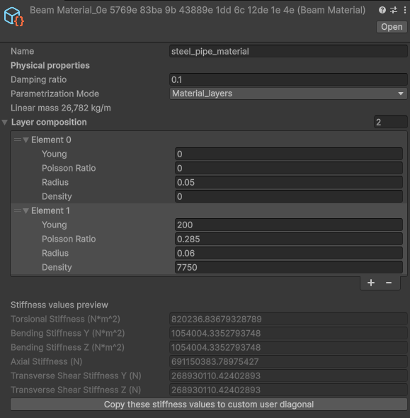
The read-only Stiffness values preview shows the results. Enter Young modulus in GPa, radius in meters, and density in kg/m³.
Layer composition
Use Layer composition to build a cable from concentric materials. Add layers from the inside out.
Enter each radius from the cable center, not from the previous layer. The radius is the layer's outer radius, not its thickness. For example, enter 0.05 m for a core and 0.06 m for a wall with an outer radius of 0.06 m; do not enter the wall thickness (0.01 m).
Each layer contributes stiffness from its annular section. The outermost radius sets the cable's visible and collision radius.
To model a hollow pipe or hose, set the innermost layer's Young modulus to 0. Set its density to the density of the contents, or to 0 for an empty void. Add the wall as the next layer. The core then contributes mass but no stiffness.
Presets
| Preset | Young modulus (GPa) | Poisson ratio | Density (kg/m³) |
|---|---|---|---|
| Rubber | 0.05 | 0.4999 | 1140 |
| Nylon | 3 | 0.4 | 1200 |
| Plastic (PVC) | 1.5 | 0.3 | 1400 |
| Aluminium | 69 | 0.246 | 2800 |
| Zinc | 90 | 0.249 | 7130 |
| Bronze | 110 | 0.35 | 8810 |
| Copper | 117 | 0.33 | 8960 |
| Iron | 208 | 0.25 | 7850 |
| Steel | 200 | 0.285 | 7750 |
User Defined Diagonal
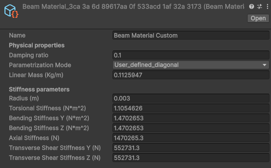
Choose this mode when you need to adjust axial and bending stiffness independently. The fields are:
| Field | Unit | Description |
|---|---|---|
| Linear Mass | kg/m | Mass per unit length. |
| Radius | m | Visual and collision radius. It does not affect stiffness. |
| Axial Stiffness | N | Resistance to stretching. |
| Bending Stiffness Y/Z | N·m² | Resistance to bending. |
| Torsional Stiffness | N·m² | Resistance to twisting. |
| Transverse Shear Stiffness Y/Z | N | Resistance to transverse shear. |
For a cable that stretches very little but bends easily, set a high Axial Stiffness and lower Bending Stiffness Y/Z. Set the Y and Z values to the same value for a round cable.
Torsional and shear stiffness
For a circular cross-section, derive torsional and shear stiffness from the axial and bending values:
Torsional stiffness        = Bending stiffness / (1 + ν)
Transverse shear stiffness = Axial stiffness / (2·(1 + ν))
Material Layers mode uses the same formulas. After you reduce the bending stiffness, recalculate the torsional and shear values.
Reducing bending stiffness
An isotropic solid rod always follows this relationship:
Bending stiffness = Axial stiffness · r² / 4
Young modulus and Poisson ratio scale axial and bending stiffness together. They cannot model a cable that is strong in tension but easy to bend. Real cables get this behaviour from their construction, for example when individual wires slide against each other.
To approximate that behaviour:
- In Material Layers mode, set a plausible material and radius.
- Click Copy these stiffness values to custom user diagonal.
- Keep Axial Stiffness unchanged. Divide Bending Stiffness Y/Z by a factor between 10 and 100 to start.
- Use the formulas above to recalculate Torsional Stiffness and Transverse Shear Stiffness.
Tune the stiffness values until the simulated cable behaves as required. If you have a measured axial stiffness for the real cable, use it instead of the value calculated for a solid rod.
Practical tuning
- If the cable oscillates instead of settling, increase Damping ratio.
- If the simulation becomes unstable, reduce the physics time-step or lower Axial Stiffness.
- If the cable looks faceted while bending, increase the number of nodes per meter.
See also
Create Cable explains presets and the basic Custom material.
Wire is a tension-only alternative when bending and torsion are not required.
Bend radius helps check whether the cable remains within a safe curvature.