![]()
Configuring Kinematic Joints
 Joints are the objects that describe the way rigid bodies move relative to each other. Kinematic joints are an essential part of any robotic system, as they allow movements.
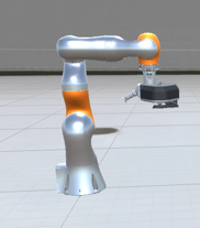
Kinematic joints can be classified into different types, based on the type of movement they allow. For example, hinge joints allow for rotational movement, while prismatic joints allow for linear movement. By combining the kinematic joints, you can create a wide range of movements and manipulate objects in a variety of ways. For example, a car's wheels are attached to the car frame by a hinge joint. They can only rotate around a specific axis. A multi-body system is thus composed of several objects connected by joints forming a kinematic chain.
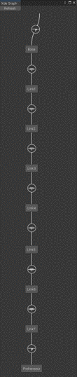
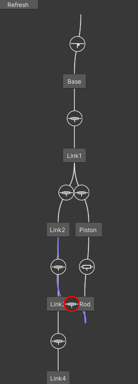
At any time, the kinematic chain can be seen from the INTERACT Menu > Physics > Show Kinematic graph.
XDE provides several types of joints :
Weldable Joint
These are commonly used joints in INTERACT for objects having 6 DOF. Weldable Joint has a unique property of being able to switch from 6 DOF to 0 DOF (and vice-versa) combining behaviours of both free and fixed joint depending its weldable state. This makes it ideal for assembly steps where a part is positioned first and rigidised later.
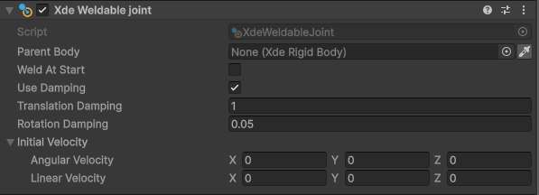
- Parent Body: preceding body in the kinematic chain.
- Weld At Start:
- Translation Damping:
- Rotation Damping:
- Initial Velocity:
- Angular Velocity:
- Linear Velocity:
Fixed Joint
A fixed joint constrains all degrees of freedom with respect to the parent object.
In the Unity inspector, a fixed joint only has one parameter: the object to which the selected object is attached to. If there is no parent object, the object is fixed with respect to the world.
A fixed joint is not necessarily static: it can be attached to a moving rigidbody.
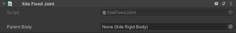
- Parent Body: preceding body in the kinematic chain.
 XdeRigidbody picking
You can use the picker icon ![]() on any XdeRigidbody field to directly pick a XdeRigidbody in your 3D view.
on any XdeRigidbody field to directly pick a XdeRigidbody in your 3D view.
Hinge Joint
A hinge joint - also called a revolute joint - only allows one rotation with respect to a specific axis.
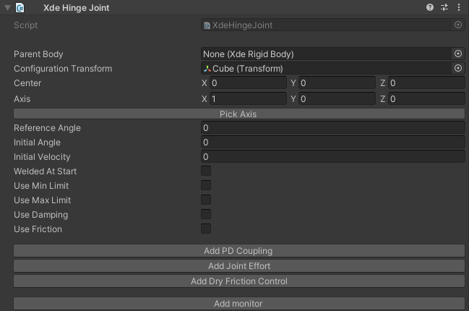
- Parent Body: preceding body in the kinematic chain.
- Configuration Transform: frame in which the axis and center of the joint is expressed (usually the object itself).
- Center: center of the joint.
- Axis: motion axis of the joint (which can be a combination of axes).
- Pick Axis: Pick joint axis from the scene view using intelligent shape detection.
- Reference Angle:
- Initial Angle: joint rotation in local frame when simulation starts.
- Initial Velocity: joint velocity in local frame when simulation starts.
- Welded At Start: Lock joint rotation when simulation starts.
- Min / Max Limit: Configure joint limits.
- Damping: add physical damping in the joint.
-
Friction: add static friction in the joint.
-
Add PD Coupling: Add spring-like control of joint.
- Add Joint Effort: Add motor-like control of joint.
- Add Dry Friction Control:
- Add monitor: Add monitor component to track joint rotation and velocity in real-time.
Hinge limits
You can set limits that exceed 360°. This way, you can create a rotation with multiple turn limits.
 Guess axis computation
The most probable hinge axis is computed during physicalization. This computation can be long on large models and can be disabled from Unity's preference window.
For scripting examples that drive hinge motion, see Driving Joints.
Prismatic Joint
A prismatic joint only allows one translation with respect to a specific axis.
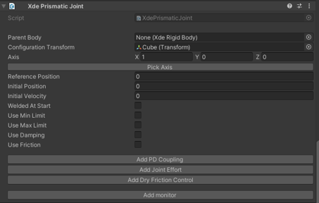
- Parent Body: preceding body in the kinematic chain.
- Configuration Transform: frame in which the axis and center of the joint is expressed (usually the object itself).
- Center: center of the joint.
- Axis: motion axis of the joint (which can be a combination of axes).
- Pick Axis: Pick joint axis from the scene view using intelligent shape detection.
- Reference Position:
- Initial Position: joint position in local frame when starting simulation starts.
- Initial Velocity: joint velocity in local frame when starting simulation starts.
- Welded At Start: Lock position rotation when simulation starts.
- Min/Max limit: configure joint limits.
- Damping: add physical damping in the joint.
-
Friction: add static friction in the joint.
-
Add PD Coupling: Add spring-like control of joint.
- Add Joint Effort: Add motor-like control of joint.
- Add Dry Friction Control:
- Add monitor: Add monitor component to track joint position and velocity in real-time.
Ball Joint
A ball joint allows 3 rotations around a specific center point.
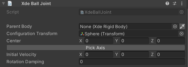
- Parent Body: preceding body in the kinematic chain.
- Configuration Transform: frame in which the center of the joint is expressed (usually the object itself).
- Center: center of the joint.
- Pick Axis: Pick joint axis from the scene view using intelligent shape detection.
- Initial Velocity: joint velocity in local frame when starting simulation starts.
- Rotation Damping: add physical damping in the joint.
Helical Joint
A Helical joint allows one rotation and one translation linked together by a constant pitch. This is the same motion as a screw.
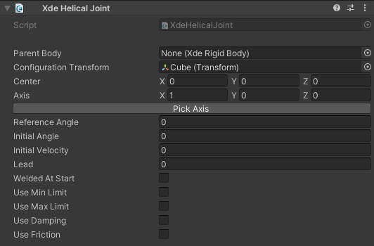
- Lead: Amount of linear travel in millimeters for a full turn.
- Min/Max limit: Angular joints limits in degrees. Since translation and rotation are linked, any limit on rotational movement will also lock the translation accordingly.
ISO metric screw
Lead is equal to pitch if your screw is single-start threadform, which is the common case. You can find pitch values for the ISO screw here.
Left-Handed threads
Unity uses an indirect coordinate systems (left-handed). The helical joint thread is therefore also left-handed. To use a right-handed thread, consider using a negative lead value.
Mapped Joint
A mapped joint allows control over a specific degree of freedom with another joint.
When the controlling unit joint position changes, the position of this joint also changes. The two positions are linked by a scale factor and an offset, using the following relation:
position_mapped = scale * position_controlling + offset
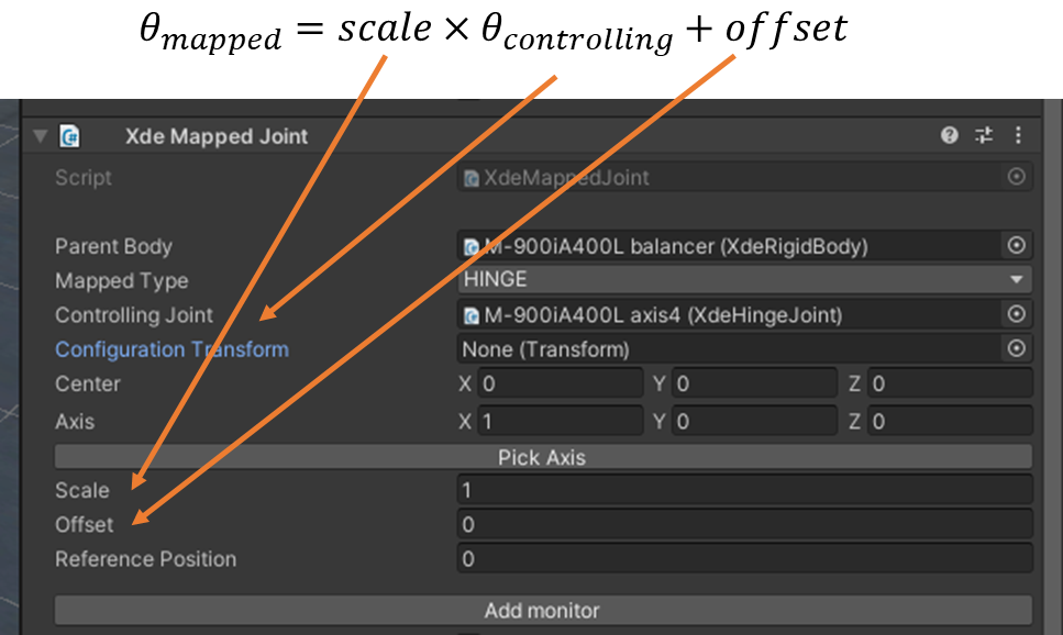
- Parent Body: the preceding body in the kinematic chain.
- Mapped Type: (options: HINGE, PRISMATIC).
- Controlling Joint
- Center: the center of the joint.
- Axis: the axis of the joint (which can be a combination of axes).
- Pick Axes: Pick joint axis from the scene view using intelligent shape detection.
- Scale
- Offset
- Reference Position:
- Add monitor: Add monitor component to track joint position and velocity in real-time.
If the map joint is a HINGE joint while the controlling joint is a PRISMATIC one, note that the conversion is 1 meter <-> 1 radian.
This joint can be used to simulate gears or belt systems.
Belt joint
You can also configure a belt joint by setting a positive ratio, which will lead to both wheels turning in the same direction.
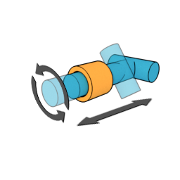
Cylindrical Joint 
There might be situations in which you need to have both translation and rotation, an example being the simulation of a door lock. You can also set custom limits on translation or rotation.
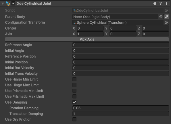
- Parent Body: the preceding body in the kinematic chain.
- Configuration Transform: the frame in which the axis and center of the joint is expressed (usually the object itself).
- Center: the local position of the axis of the joint (which can be a combination of axes).
- Axis: the rotation (and translation) axis of the joint (which can be a combination of axes), in local coordinates.
- Initial Position: joint position in local frame when starting simulation starts.
- Rotation Damping: add physical damping in the joint (rotation).
- Translation Damping: add physical damping in the joint (translation).
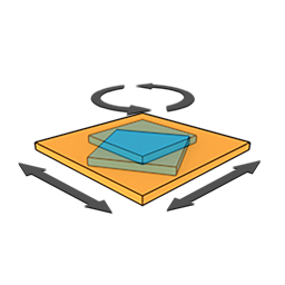
Planar Joint
If you need to constrain on a plane and also allow rotation, you should use this joint. Note that there are no limits on this joint.
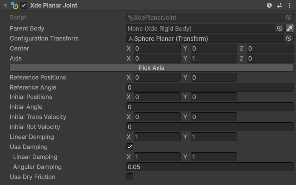
- Parent Body: the preceding body in the kinematic chain
- Planar Frame: the frame in which the axis and center of the joint is expressed (usually the object itself).
- Center: the local position of the axis of the joint (which can be a combination of axes).
- Reference Position: the target position towards which the current position moves, at any time of the simulation (if it's different to the initial position, you need to have a damping other than zero).
- Initial Position: the position of the joint at the beginning of the simulation.
- Initial Angle: the orientation of the joint at the beginning of the simulation.
- Angular Damping: add physical damping in the joint (rotation).
- Linear Damping: add physical damping in the joint (translation).
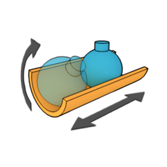
Point on Line Joint
You should use this joint if you need to constrain translation along a single axis, but additionally require complete freedom to rotate around all axes. This joint constrains translation in the same way that a prismatic joint does. Rotation is however not constrained at all, which is what differentiates a point on line joint from a prismatic joint.
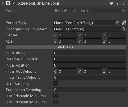
- Parent Body: the preceding body in the kinematic chain.
- Configuration Transform: the frame in which the axis and center of the joint is expressed (usually the object itself).
- Center: the local position of the axis of the joint (which can be a combination of axes).
- Axis: the axis of the joint (which can be a combination of axes).
- Reference Position: the target position towards which the current position moves, at any time of the simulation (if it's different to the initial position, you need to have a damping other than zero).
- Initial Position: the position of the joint at the beginning of the simulation.
- Initial Rotation Velocity: the angular velocity of the joint at the beginning of the simulation.
- Initial Translation Velocity: the translation velocity of the joint at the beginning of the simulation.
- Damping: add physical damping in the joint.
- Translation Damping: add physical damping in the joint (translation).
- Min/Max Prismatic Limit: to configure the joint's translation limits.
Free Joint
A free joint moves freely along and between the axes of the six degrees of freedom (meaning that it can freely rotate and translate). If gravity is enabled, the object will be in free fall.
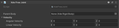
- Parent Body: the preceding body in the kinematic chain.
- Velocity
- Angular Velocity: Angular velocity of the joint at the beginning of the simulation.
- Linear Velocity: Linear velocity of the joint at the beginning of the simulation.
Pick Axis
Joint axis is set in the configuration transform local pivot frame. To ease the selection of your joint axis we have introduced the Pick Axis tool. It allows you to pick a specific surface or edge of your part directly from the 3D scene like in your favorite CAD software:
Pick axis
While using the pick axis tool, you can press I to invert the direction of the detected axis.
Triangle mode 
When complex shapes are not detected, switching to triangle mode detection might help. Using Shift+T allows users to select the normal of a Triangle. Use again Shift+T to get back to shape detection.
-
Initial angle/position: initial angle/position at runtime. For instance, if you want your robot to be in a given configuration when starting the simulation. The initial configuration must stay between joint limits.
-
Reference angle/position: The reference angle/position is an offset along the joint axis. You can use it to have the same frame in both your INTERACT simulation and in your real world model. You can then use the same angle or distance value for your joint. Changing the reference angle/position shifts the initial and limits position accordingly.
Closed Loop
Closed-loop dynamics refers to the relationship between the motion and force of closed-loop mechanisms.
A robot mechanism is said to be closed loop if it includes one or more kinematic loops, which are cycles in the mechanism’s connectivity graph.
Creating a Closed Loop
Multiple joints cannot be attached to the same object. To create the closing joint, use INTERACT > Physics > Create closed loop on the object that needs an additional joint. This creates an empty child GameObject with only a joint component (no XdeRigidbody component) that connects your two final bodies via Child body and Parent body fields.
Multiple joints
It is not possible to add multiple joints on the same gameobject to combine movements. In order to combine joints, you must create additional gameobject, even if they are just empty.
Handling Over-constrained Systems
A common issue is that the closed-loop system becomes over-constrained (hyperstatic). The mechanism may lock up or not move despite correct configuration. This happens when multiple constraints block the same degrees of freedom (often due to misaligned axes).
We should make the system isostatic (exactly constrained) by progressively adding degrees of freedom. Keep the closing joint as a hinge if possible, and modify other joints in the loop using this strategy: 1. Try replacing a hinge with a Cylindrical joint (+1 DOF: translation along the joint axis) 2. Try replacing a hinge with a Ball joint (+2 DOF: free rotation, useful if translation is already constrained) 3. Replace a hinge with a Point on Line joint (similar to prismatic but with free rotation)
Replace a joint
Use SHIFT+P to re-physicalize an XdeRigidbody and select a different joint type. Axis and limits are preserved when applicable (e.g., a Point on line joint keeps the axis from a replaced Hinge joint).
Joint constraints
A joint constraint cannot be actuated or monitored. Use Driving Joints for actuated motion.
Weld Property
Changing the kinematic graph at runtime is normally not supported. You can only tune existing joint properties such as limits or damping. Welding provides a controlled way to lock or unlock a joint without rebuilding the physics rig.
What Welding Does
- A welded joint becomes fixed to its kinematic ancestor, matching the behaviour of a fixed joint.
- Leave the Parent Body field empty to weld a part directly to the environment.
- A Weldable Joint starts unlocked so the child body behaves like it is mounted on a free joint until you weld it. This makes it ideal for assembly steps where a part is positioned first and rigidised later.
Runtime API
Use the XdeWeldableJoint component to switch between free and fixed behaviour during simulation:
var weldableJoint = GetComponent<XdeWeldableJoint>();

weldableJoint.Unweld();
weldableJoint.SetParent(targetBody);
weldableJoint.Weld();
Always call Unweld() before SetParent(). Once welded, the joint remains locked until you explicitly call Unweld() again.
Common Use Cases
- Lock a mechanism when it reaches a target pose without re-physicalizing the assembly.
- Attach loose parts during virtual assembly before handing control back to an operator or robot.
- Combine with scripts that drive motion—see Driving Joints—to automate the transition between free and fixed states.
Weldable joint
Prefer a Weldable Joint over a Free Joint when you need runtime flexibility.