Import CAD files#
XR Twin can process and import a wide range of 3D files covering most of the major industrial CAD files standards (see supported formats at the end of this section).
To import a 3D file, select Object/Import from the menu or click on the Import button  from the side bar and select the CAD file.
Import settings#
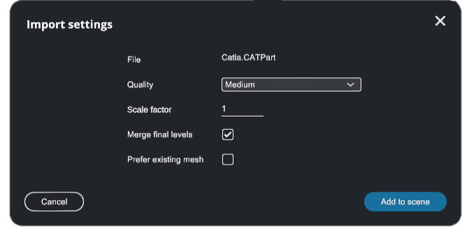
The settings used to import a 3D model will impact the performance of your simulation. There is no set of preferences that will work every time, as every use-case is different.
- Quality (only for B-Rep type objects): defines the mesh quality (triangle density) of the imported model. A higher quality means more triangles computed from the original object, hence more precision and quality in the simulation but less performance.
-
Scale factor: XR Twin default unit is meters. Modify scale factor if the imported file was designed with a CAD software with different unit system.
-
Up Axis: Choose the Up Axis based on the upward axis of the source application. You can select the Z Axis (the default option) or the Y Axis.
-
Merge final levels: Sometimes, objects created from CAD software are delivered as multiple sub-surfaces disconnected from one another, while they should be unified as a single object. Use this setting to assemble together unconnected CAD surfaces of hierarchy nodes into one single object.
-
Prefer existing mesh: some CAD files may already contain a polygonal representation (usually low quality) for visualization purposes. If the 3D loader fails to compute triangle sets for the given part, use this setting to import the embedded polygonal representation.
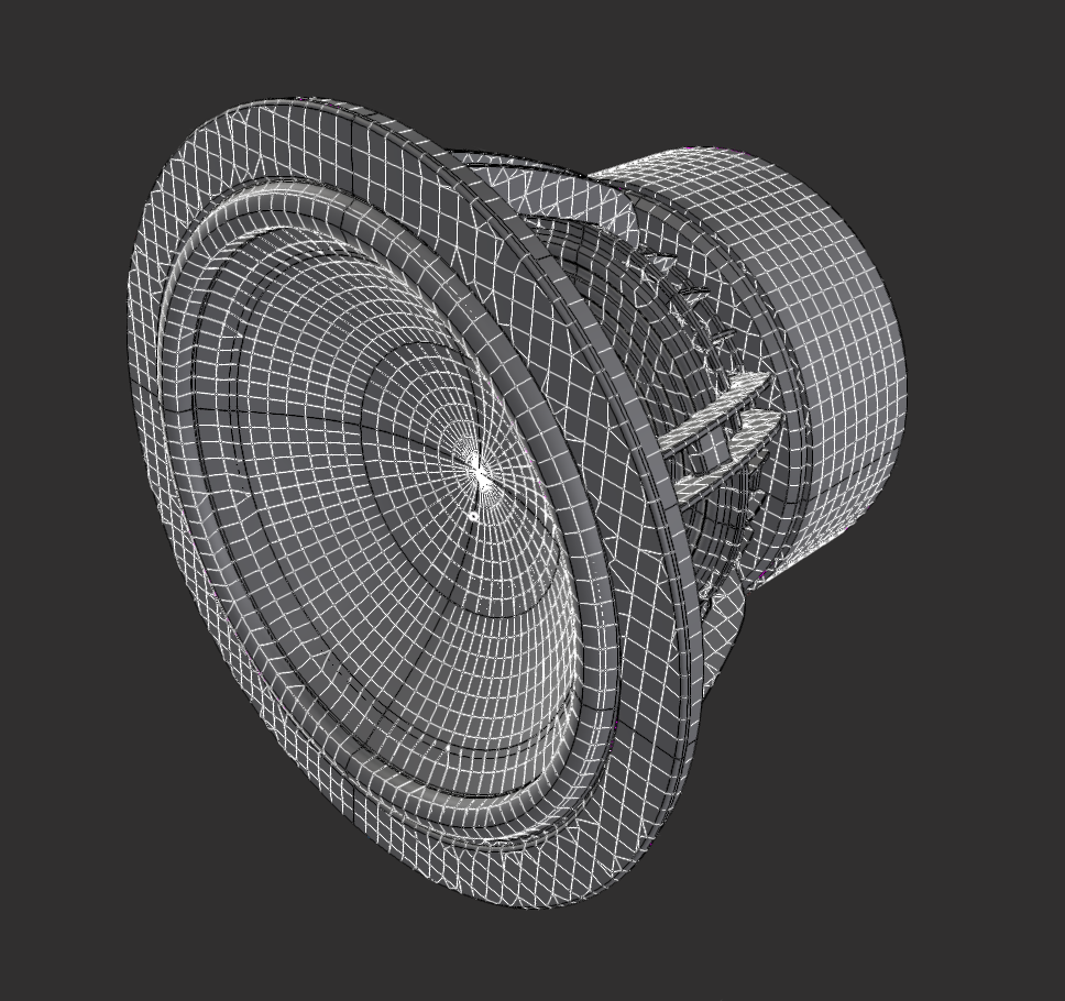
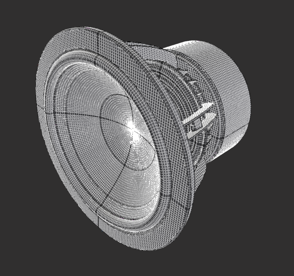
B-Rep Vs Meshes#
There are two primary file types you can use for importing 3D objects: BRep and mesh files. It is important to understand the difference between these file types and in general, use BRep type files when possible (native file formats).
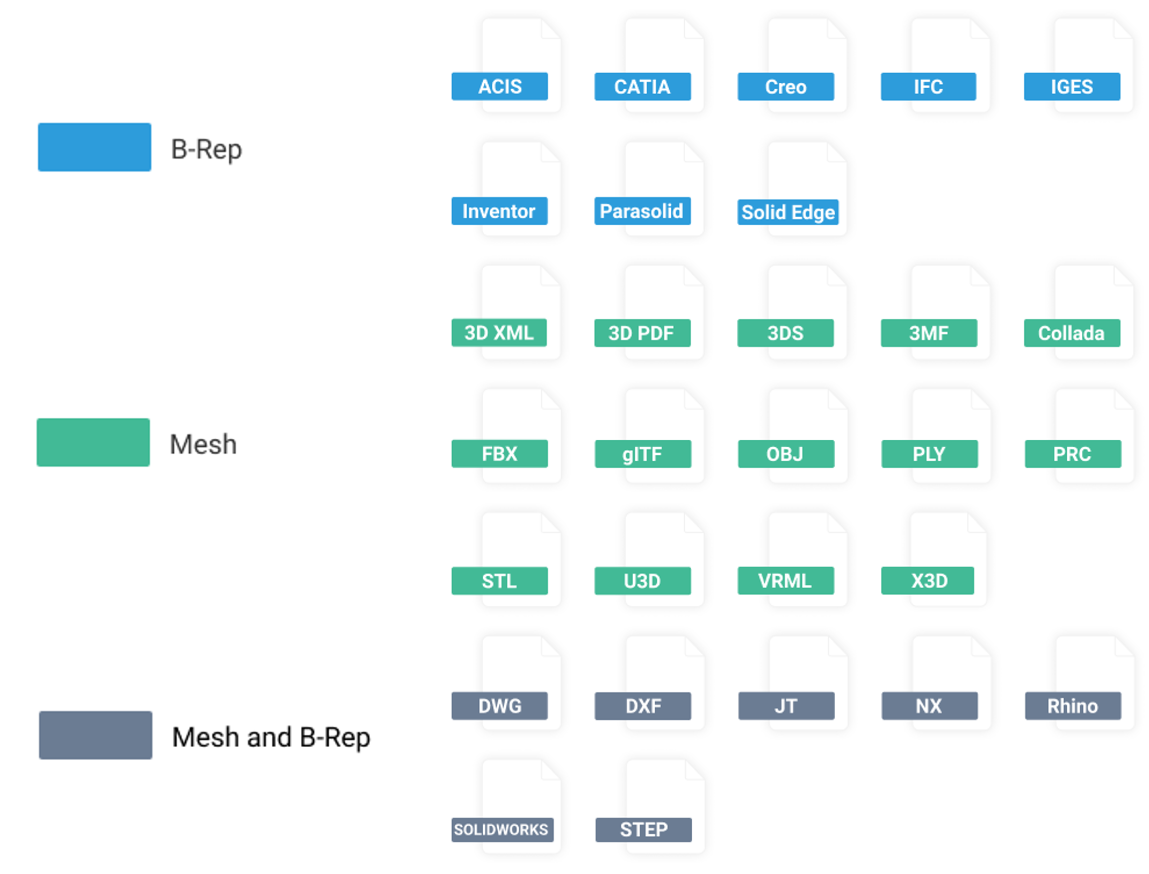
BRep (Boundary Representation) files describe 3D objects using precise geometric and topological information. BRep files define the shape, dimensions using mathematical equations (e.g. a cylinder is represented by a length and a radius). BRep files are commonly used in CAD (Computer-Aided Design) applications (CATIA, Solidworks, Siemens).
When importing BRep files into XRTwin, the software will interpret and convert the BRep data into a set of polygons, suitable format for rendering and interaction within the virtual reality environment.
Mesh files, on the other hand, represent 3D objects using a collection of interconnected polygons. This polygonal representation is also often referred to as faceted, tessellated or triangulated. Meshes provide a simplified representation of the object's geometry by approximating its surfaces. The number of triangles in the polygonal representation depends on accuracy used when approximating the original precise B-Rep representation.
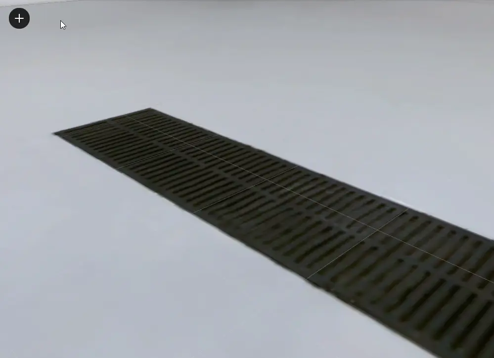
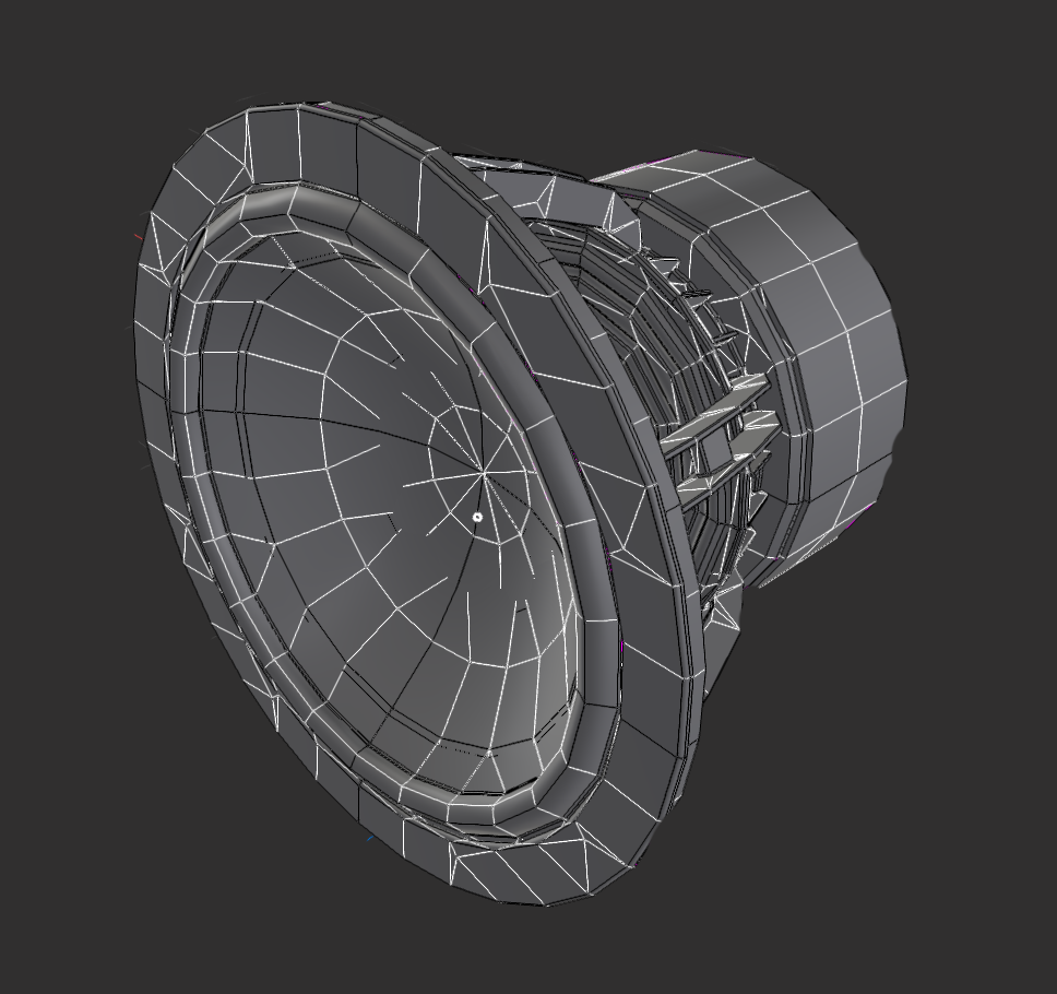
The images below demonstrate the same object in B-Rep or mesh format.

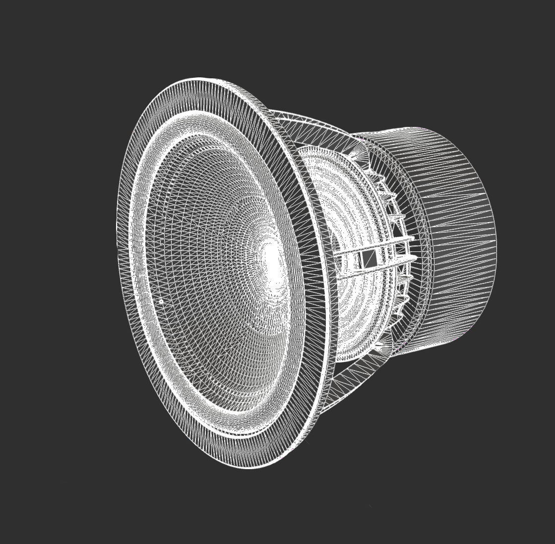
Recommendation For relevant workflow, the imported model should come from a Brep file type (native CAD format). This allows you to properly set the resolution of the triangulated model on import and ensures that no valuable information (structural, hierarchy) is lost.
Model analysis and shape detection#
After importing a model in the scene, a background process will analyze the parts and compute possible shapes from the topology that can be used later on for defining mechanical constraints, measure points and so on. These process might take some time and status is indicated by the progress bar at the bottom of the hierarchy panel. The part features are then stored in the project so XR Twin does not have to recalculate part shapes when reopening a project.
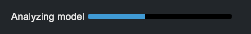
Degraded performance during model analysis
Analyzing a complex assembly can be performance consuming. Degraded XR Twin performance may occur during this process so it is advised to wait for the end of the analysis before launching the simulation.
Move part origin#
You can edit the origin of your part local frame. This is useful for scenario authoring when part origin is far from the 3D model and you have trouble to align the object to its target.
To move the origin of the part:
- Right click on the desired node in the working tree
- Click on Move Origin
- Select a new origin in the 3D view
Working with large assemblies#
When working with large 3D models in XRTwin, it is important to optimize your scene for optimal performance. Here are some best practices to follow:
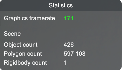
- Assess Graphics Frame Rate#
After importing a model, open the statistics panel  in XRTwin to assess the graphics frame rate.
This metric indicates how many images are rendered per second.
If the frequency is too low, it may be due to the presence of too many objects in the scene, which can impact performance.
in XRTwin to assess the graphics frame rate.
This metric indicates how many images are rendered per second.
If the frequency is too low, it may be due to the presence of too many objects in the scene, which can impact performance.
- Merge Static Objects#
Consider merging together objects that serve only for decoration and won't be interacted with. This practice helps reduce the overall complexity of the scene during the real time simulations. Two tools are available:
- Merge in the contextual menu
- Optimize in the tool bar
To merge child-objects below a selected parent:
- Right-click on a parent node in the Hierarchy tab,
- Select "Merge" in the contextual menu,
- A new node named "Group" is created, who contain the selected hierarchy.
- This local process combines all the child nodes of the selected parent into a single "Group" entity, reducing the number of draw calls and improving performance. This action can be reversed: right-click on the "Group" node and select "Unmerge" in the contextual menu.
To merge all static tree structures to optimize your scene:
- Click the "Optimize Scene"
 tool to the right of the tool bar.
 - This tool analyze your scene and display the result in the Optimize pop-up: number of candidate objects (they must be "static", without physicalized object in their hierarchy) ), number of groups to be created (one per hierarchy), and recommendations.
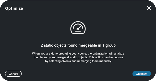
- Click Optimize.
- This global process combines all the child nodes of the candidate parents into multiple "Group" entities (one per bunch), reducing the number of draw calls and improving performance. This action can be reversed locally: right-click on of the "Group" nodes and select "Unmerge" in the contextual menu.
When is a hierarchy element mergeable ?
There are two conditions for a hierarchy element to be mergeable:
(1) Parent node
The Merge option is only available when you select a parent node. If you select a node that has no children, then Merge is not selectable. It's the same when the last multi-selected object has no children. Note that multi-selection is not available; only the last valid node selected is merged.
(2) No physicalized child
For both tools, the process cannot succeed if a physicalized object is present in the child objects. If this is the case, the Merge option will not appear in the context menu and the whole object will not be counted in the Optimize analysis.
Merging size limit
You will be notified when merging an object exceeds the size limit of 2 GB.
- Adjust the Level of Detail (LOD)#
In 3D graphics, Level Of Detail or LOD is an optimization technique that hides small objects that are far away from the point of view. XRTwin allows you to adjust the Level of detail setting in the project's Preferences pop-up (from the menu bar, select Project>Preferences>Graphics). By optimizing the LOD, you can reduce the number of rendered objects, improving performance without sacrificing visual quality.
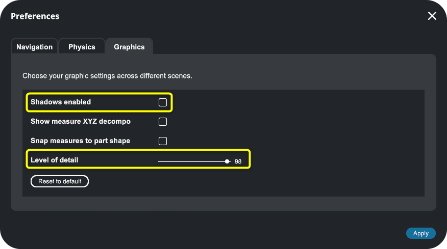
- Disable Shadows#
While shadows - in this case ambiant occlusion - can enhance realism and create a sense of depth to your scene, they can also be computationally expensive. If you're experiencing performance issues with large 3D models, consider turning off shadow rendering. This setting can be adjusted in your project's preference panel (from the menu bar, select Project>Preferences>Graphics and uncheck "Shadows enable").
By following these optimization techniques, you can ensure that your large 3D models run smoothly in XRTwin, providing an immersive and efficient virtual reality simulation experience.
Supported CAD files formats#
| Format | Extensions | Supported versions |
|---|---|---|
| 3D PDF | All | |
| 3D XML | .3dxml | Version 4.0 - 4.3 |
| 3DS | .3ds | All |
| 3MF | .3mf | All |
| ACIS | .sat, .sab | R2.0 and newer |
| CATIA | .CATPart, .CATProduct, .cgr | V5 and V6 |
| COLLADA | .dae | All |
| AutoCAD 2D | .dwg | All |
| AutoCAD 3D | .dwg, .dxf | All |
| Autodesk FBX | .fbx | 2012 and newer (versions 7.2, 7.4, and 7.5) |
| glTF | .gltf, .glb | 2.0 |
| IFC | .ifc | IFC 2x Editions 3 and 4 |
| IGES | .igs, .iges | All |
| Inventor | .ipt, .iam | 2015 to 2026 |
| JT | .jt | v8.x to v10.x |
| OBJ | .obj | All |
| Open Cascade | .brep | All |
| Parasolid | .x_t, .x_b | All |
| PLY | .ply | All |
| PRC | .prc | All |
| PTC Creo | .prt, .asm | Up to 12 |
| Rhino 3D | .3dm | Up to 7 |
| SIEMENS NX | .prt | Up to 2506 |
| Solid Edge | .asm, .par, .psm | All |
| Solidworks | .sldprt, .sldasm | 2004 to 2025 |
| STEP | .stp, .step | AP203, AP214, AP242 |
| STL | .stl | All |
| U3D | .u3d | All |
| USD | .usd, .usda, .usdc, .usdz | All |
| VRML | .wrl | V1/1995 and v2/1997 |
| X3D | .x3d | All |
Export STEP from Solidworks
When exporting STEP files from Solidworks, use STEP AP214 or later version AP242 as "Save As Type" and enable "Export Appearances" in the export options if you need colors and textures.
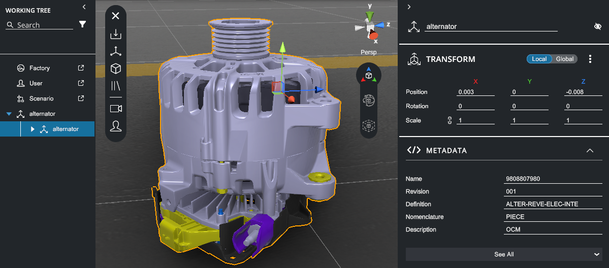
Metadata#
Starting with version 25.1.0 in April 2025, XRTwin can read part metadata from the following formats: ACIS, CATIA, GLTF, IFC, IGES, JT, NX, Parasolid, Revit, SolidWorks, STEP, and X3D.
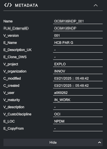
To view the metadata of a CAD node, select it and view the METADATA section in the Property panel. The first six entries are displayed. Click See All to display all entries, Hide to collapse.
Limited string size
During import, keys and values are limited to a maximum of 1024 characters. If a string exceeds this limit, it will be truncated and only the first 1024 characters will be retained.
AutoCAD drawings#
Starting with version 25.1.0 in April 2025, XRTwin can import AutoCAD .dwg 2D drawings as bleuprints, displayed as colored, scaled lines for layout integration.
Bleuprints can help you to position 3D elements in your scene.

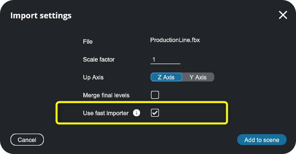
Super fast FBX importer#
Starting with version 25.1.0 in April 2025, you can use a custom FBX importer pipeline as an alternative to the standard importer. This option offers unmatched speed, for example, rendering a nuclear facility with 100K objects in 20 seconds. This option is enabled by default. This FBX importer is still in the experimental stage.