Physics and Interactions#
What is a Physics Engine?#
A physics engine is a software component that simulates physical phenomena, such as motion, forces, and collisions, in a virtual environment. In XR Twin, the physics engine is responsible for calculating the behavior of objects in the scene, based on their physical properties and the interactions between them. Some examples of physics behavior provided by XR Twin physics engine:
- Collision between objects
- Part mobilities and constraints
- Gravity
- Friction properties
- Part grabbing and manipulation
Adding Physics to objects#
By default, when 3D objects are imported into XR Twin, they have no physical properties assigned to them. This means that they cannot be interacted with or affected by the laws of physics in the scene. To add physics behavior to an object, follow these steps:
- Select the object.
- Click on the
 button at the bottom of the Inspector panel (or type the keyboard shortcut P).
 - Choose the type of mobility or constraint you want to assign to the object (see joint types).
- Configure the physical properties of the object, such as mass, friction, motion constraints in the Inspector.
This object is then transformed into a so called Rigid Body, recognized in the hierarchy by this icon  .
When launching the simulation, Rigid Bodies will behave according to the laws of physics and the chosen mobility type (joint).
They will react to collisions as well as its children in the hierarchy.
.
When launching the simulation, Rigid Bodies will behave according to the laws of physics and the chosen mobility type (joint).
They will react to collisions as well as its children in the hierarchy.
Removing physics properties
Remove physical properties to an object by clicking on the  icon next to the Physics component. Alternatively, you can use the Dephysicalize command in the Object menu.
The object will then loose physical properties and collisions and become a static 3D object again.
icon next to the Physics component. Alternatively, you can use the Dephysicalize command in the Object menu.
The object will then loose physical properties and collisions and become a static 3D object again.
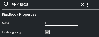
Configuring Rigid Body Properties#
To obtain a realistic simulation in XR Twin, it's important to configure the physical properties of each physicalized part in the scene carefully.
- Mass: the mass of the object in kg. Objects with a higher mass will be harder to move and will require more force to accelerate.
- Enable gravity: defines whether of not the object is affected by gravity.
Configuring kinematic joints and constraints#
In addition to assigning physical properties to objects in the scene, XR Twin also supports part joints and constraints to simulate the relationships between objects. Joints are connections between two objects that allow them to move relative to each other, while constraints are limits or conditions on the motion of a part. By combining kinematic joints, you can create a wide range of movements and manipulate objects in a variety of ways. A multi-body system is thus composed of several objects connected by joints forming a kinematic chain.
Types of Joints#
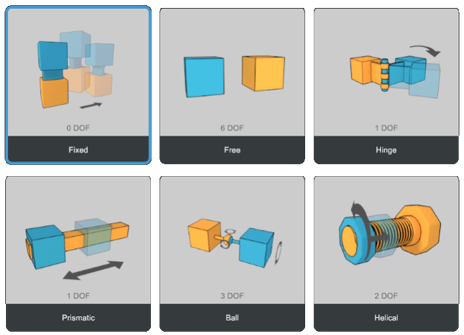
XR Twin supports six basic types of part joints, each with different degrees of freedom and properties that can be configured in the Inspector:
1. Fixed Joint#
A fixed joint locks all degrees of freedom with respect to the parent object.
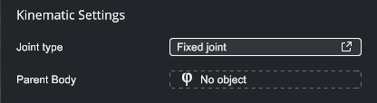
In the Inspector, a fixed joint has only one parameter :
- Parent Body : the object to which the selected object is attached to (drag a rigid body from the hierarchy).
If there is no parent object, the object is fixed with respect to the world.
A fixed joint is not necessarily static: it can be attached to a moving rigid body.
2. Free Joint#
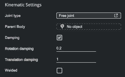
A free joint moves freely in the six degrees of freedom (can freely rotate and translate). If gravity is enabled, the object will be in free fall.
- Parent Body: the object to which the selected object is attached to (drag a rigid body from the hierarchy).
- Damping: add physical damping in the joint. Damping is a force linearly proportional to velocity acting in the direction opposite to the direction of motion.
An object with free joint is subject to:
- Check Damping to activate damping options.
- Rotation damping opposing rotations (Nm/(rad.s-1)).
- Translation damping opposing translations (N/(m.s-1)).
- Welded: whether or not the object is welded to its Parent (rigid) Body.
3. Hinge Joint#
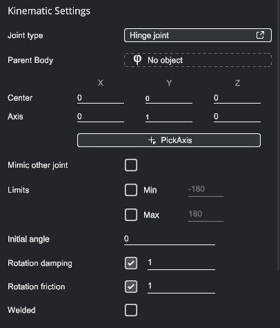
A hinge joint - also called a revolute joint - allows only one rotation around a specific axis. You can specify the anchor point and axis of rotation, as well as limits on the angle of rotation.
- Parent Body: the object to which the selected object is attached to (drag a rigid body from the hierarchy)
- Center: the center of rotation
- Axis: the axis of rotation (can be a combination of axis)
- PickAxis: see PickAxis below.
- Mimic other joint: see Mimic below.
- Min/Max limits: angular joint limits in degrees
- Initial angle: the angle of the joint at the beginning of the simulation
- Rotation damping: add physical damping in the joint (Nm/(rad.s-1)). This will create an opposite torque proportional to the angular velocity.
- Rotation friction: add static friction in the joint (Nm). The object will start rotating if the external torque is greater than the static friction value.
- Welded: whether or not the object is welded to its Parent (rigid) Body.
4. Prismatic Joint#
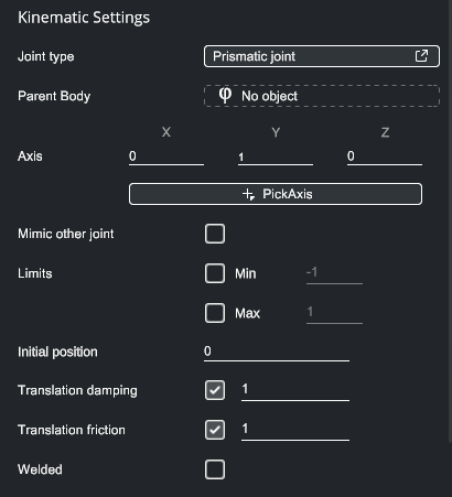
A prismatic joint allows only one translation (linear movement) along a single axis, like a sliding door. You can specify the anchor point and axis of motion, as well as limits on the range of motion.
- Parent Body: the object to which the selected object is attached to (drag a rigid body from the hierarchy).
- Axis: the axis of the joint (can be a combination of axis).
- PickAxis: see PickAxis below.
- Mimic other joint: see Mimic below.
- Limits Min/Max: linear joint limits in meters.
- Initial position: the position of the joint at the beginning of the simulation.
- Translation damping: add physical damping in the joint (N/(m.s-1)). This will create an opposite force proportional to the linear velocity.
- Translation friction: add static friction in the joint (N). The object will start translating if the external force is greater than the static friction value.
- Welded: whether or not the object is welded to its Parent (rigid) Body.
5. Ball Joint#
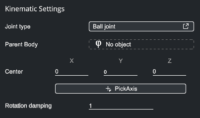
A ball joint allows three rotations around any axis, like a ball and socket joint in the human body. You can specify the anchor point and rotation damping.
- Parent Body: the object to which the selected object is attached to (drag a rigid body from the hierarchy).
- Center: the center of rotation.
- PickAxis: see PickAxis below.
- Rotation damping: add physical damping in the joint (Nm/(rad.s-1)). This will create an opposite torque proportional to the angular velocity.
6. Helical Joint#
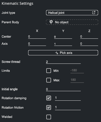
A helical joint allows one rotation and one translation linked together by a constant pitch. This type of joint is useful for modeling screws, and other mechanisms with rotating and translating parts. You can specify the anchor point, axis of rotation and translation, and limits on the range of motion.
- Parent Body: the object to which the selected object is attached to (drag a rigid body from the hierarchy).
- Center: the center of rotation.
- Axis: the axis of rotation (can be a combination of axis).
- PickAxis: see PickAxis below.
- Screw thread: the linear travel (mm/round) the object makes per one object revolution.
- Limits Min/Max: angular joint limits in degrees.
- Initial angle: the angle of the joint at the beginning of the simulation.
- Rotation damping: add physical damping in the joint (Nm/(rad.s-1)). This will create an opposite torque proportional to the angular velocity.
- Rotation friction: add static friction in the joint (Nm). The object will start rotating if the external torque is greater than the static friction value.
- Welded: whether or not the object is welded to its Parent (rigid) Body.
By carefully configuring part joints and constraints in XR Twin, you can create complex mechanical systems and simulate real-world physics with high accuracy.
Mimic Joint#
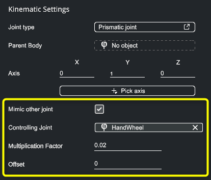
A mimic joint is used whenever a joint motion is based on another joint, such as gears or a rack and pinion system.
To add a mimic joint:
- Simply check the Mimic other joint option,
- Specify the Controlling joint,
- Set the Multiplication Factor between the master joint and the slave joint. Ex: Set -1 for gears that turn in opposite directions at the same speed, and -2 if one gear is larger and turns twice as fast.
Kinematic axis#
When setting a new joint, users can configure the kinematic axis of this joint using the Pick Axis button in the Kinematic settings section of the joint. When doing so, XR Twin's shape detection feature suggests axis and faces while hovering the 3D model with the mouse. Use left click to confirm your axis selection.
Contact arrows#
XR Twin's Physics Engine computes collision between rigid bodies. Users can choose to display contact arrows on contact points. From the menu, check Project > Preferences > Physics > Show contact arrows.
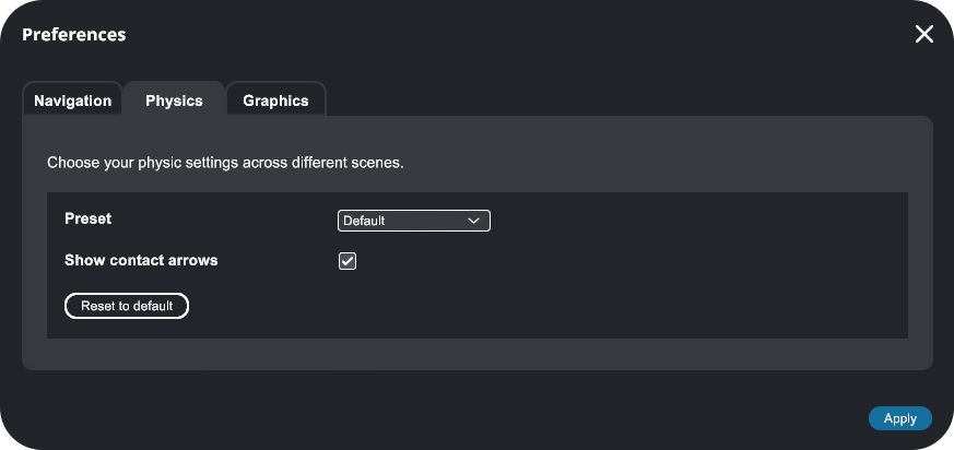
Collision arrows are yellow. Contact arrows are red.
Joint Actuator#
It is possible to add an actuator to a joint. This allows to control your joint in position and/or velocity using a target value and a gain.

Some examples:
- Uniform translation of boxes on a conveyor. Use Velocity with a Prismatic joint.
- Uniform rotation of helicopter blades. Use velocity with a Hinge joint.
- An automatic door closer. Use Velocity with a Hinge joint.
- Emergency push button. Use Position with a Prismatic joint.