Create Step-by-Step Scenarios#
The Scenario Builder popup allows users to configure scenarios by defining the required steps to complete a task or achieve a specific objective. With this feature, users can define a series of steps and actions to simulate real-world situations and guide trainees through specific tasks or workflows. This is especially valuable for applications such as maintenance procedures, assembly instructions, and operational guidelines.
Preparing your scene#
Before starting with scenario creation, ensure your scene is fully prepared:
- All necessary 3D models and environments should be imported and properly positioned.
- Make sure that all objects that will be manipulated throughout the scenario are interactable (physicalized) and correctly setup (Ex: limits, damping, parenting).
- Confirm that interactions with objects are correctly set up to allow smooth functioning during the scenario execution.
Accessing the Scenario Builder#
Each XRTwin project includes a Scenario GameObject in the Hierarchy. To begin creating or editing a scenario, follow these steps:
- Select the Scenario object in the Hierarchy panel (left).
 ,
, - In the Inspector panel (right), in the Scenario component, click on the
 button.
Alternatively, you can click the Quick Edit button
button.
Alternatively, you can click the Quick Edit button  next to the Scenario object in the Hierarchy for quicker access.
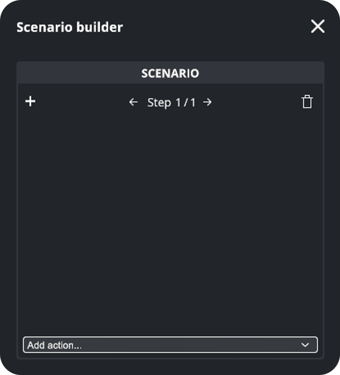
 - This will open the Scenario Builder pop-up where you can configure and define steps and actions for your scenario.
Adding steps and actions to the Scenario#
A scenario is composed of a series of steps that must be completed to achieve a specific goal. Each step consists of multiple "elementary" actions that guide the user through the task. All step actions must be validated to complete the step.
For example, in an engine maintenance scenario, you might have the following steps that could include several actions:
| Steps (examples) | Actions (examples) |
|---|---|
| First Step: "Perform engine inspection" |
"Watch video instructions" "Remove engine cover" "Inspect spark plugs" "Tighten bolts on cylinder head" |
| Other Step: "Check levels" |
"Listen to audio instructions" "Check oil level" "Check windshield washer fluid levels" |
During the execution of the scenario, the system will proceed to the next step only when all actions in the current step have been successfully completed.
Users can manage steps and manage actions to them within the Scenario Builder pop-up.
Manage steps#
- Add a Step#
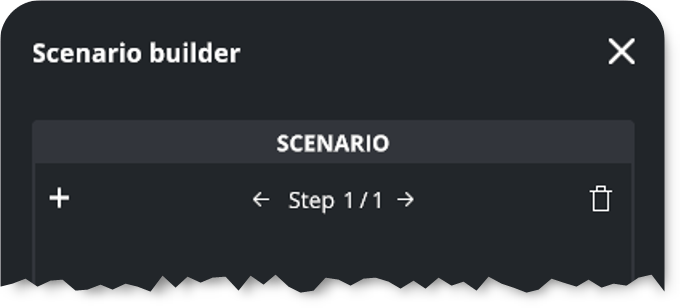
To add (or insert) a new step to the scenario, click on the + button left to the current step name. An empty step is added just after the current one.
- Select a Step#
To navigate to a specific step, click on the left arrow (go to previous step) or the right one (go to next step) 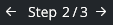 . The current step is identified by its rank (the first number) and total (the second number).
- Delete a Step#
To delete a step, click the "Trash" button  next to the current step name. Be careful: all the step's actions are also deleted. This action is not undoable.
Manage actions#
Users can manage actions within the Scenario Builder pop-up:
- Add actions to a step#
To add new actions to a step, open Scenario Builder popup.
-
Select a step.
If needed, to add or insert a new step, to navigate between your steps or to delete one, see Manage Steps above. -
Dropdown the Add action... list
 .
. -
Select an Action among the 5 available.
-
Complete its parameters according to type of action (see Actions library).
- Disabling an action#
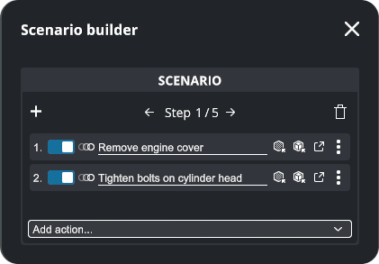
Toggle the Action On or Off as needed  .
.
- Renaming an action#
Rename Action for better clarity and organization  . The Action name is displayed in the Task list.
- Identify action's target#
Click  to focus on the Target, which will blink three times.
- Identify action's object#
Click  to focus on the Object, which will blink three times.
- Edit an action#
Click  to open the Action pop-up (depending on the action type) and edit the action parameters.
- Open action's mini menu#
Click on the three dot icon  to display additional features in a mini menu:
- Move to...#
Move the concerned action to another step to refine the sequence and flow of the scenario:
- Click on the three dot icon to open action's mini menu
- Fly over Move to...
- Select destination step from among those listed
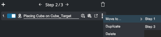
- Duplicate#
Make a copy of the concerned action, in the same step.
- Delete#
Delete the concerned Action. This is not undoable.
Scenario Parameters#
When configuring your scenario, you can adjust various parameters to enhance the user experience and provide additional guidance during the simulation.
Select the Scenario GameObject in the Hierarchy panel. Scenario's properties are displayed in the Inspector (right panel) in Design mode and Simulation mode.
Controls in Design mode#
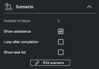
When in Design mode, the available parameters in Scenario component include:
- Show Assistance (Design)#
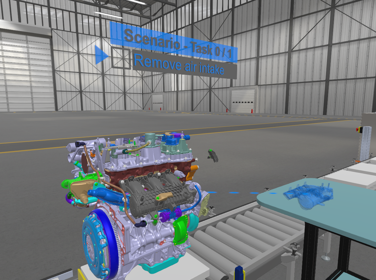
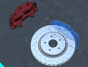
Displays visual aids that guide users on where to place objects within the scene. You can toggle these visual aids on or off at any point during the scenario execution. This feature is composed of:
- A blue ghost visualization of where the part should be positioned in the final assembly,
- A blue guideline that links the part’s current position to its target destination,
- Loop After Completion#
Automatically restarts the scenario back to Step 1 after it has been completed,
- Show Task List#
Displays a list of the current action(s) in the 3D view, showing the tasks the user must perform. You can customize the names of these actions directly in the Scenario Builder.
- Edit scenario#
Click to open the Scenario Builder popup.
Controls in Simulation mode#
During Simulation mode, in addition to the ability to show/hide assistance as in Design mode, two additional buttons will appear in the Scenario component:
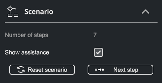
- Number of steps#
Number of steps in the scenario.
- Show assistance (Simu)#
Same as in Design mode. See above.
- Reset Scenario#
Click Reset Scenario button to restart the scenario from the beginning and reposition all parts to their initial positions (only parts related to the scenario are affected). This enables the simulation to be repeated as many times as required.
- Next Step#
This forces the scenario to ignore current step and skip to the next one.
Actions library#
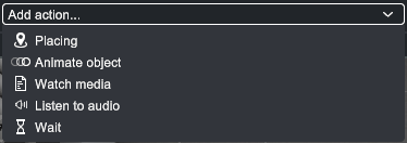
There are 5 elementary action types you can add to a step: Placing, Animate Object, Watch Media, Listen to audio and Wait (see below).
From these individual elements, users can create a linear sequence of actions that form a comprehensive scenario. Additionally, users can manage actions within the Scenario Builder pop-up (see below Manage Actions).
- Placing (action)#
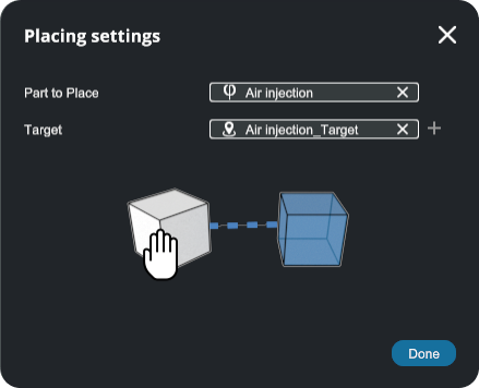
Purpose: The Placing action allows the user to grab and move a part from its current position to a specific position/rotation target. For example, "Remove engine cover" could involve physically lifting the cover off the engine.
The Placing action requires two main elements: a part and a target.
Part to Place#
Select the part (an object) in the Hierarchy and drop it in the Part to Place slot. The part must be physicalized first.
Target#
Select the part's Target in the Hierarchy and drop it in the Target slot.
 #
#
If the target is not already in the scene, you can create one by clicking the + icon next to the target field  .
.
A new object is added to the Hierarchy. It will have the same name as the object with the "_Target" suffix.
Done#
Click to validate, close the pop-up and return to Scenario Builder.
Placing Target component#
When selected, the Target will show a blue ghost of the corresponding part in the Scene View. Use the Target's gizmo to move the target to the desired final position/rotation of the part.
When selected, the Target component is displayed in the Inspector panel (image below).
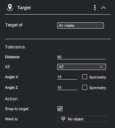
The Target can be configured with the following parameters:
Target of#
The name of the linked part. Cannot be modified.
Distance#
Defines how close the origin of the part must be to the origin of the target for the action to be considered complete (in meters).
Axis#
Scroll down the list to select the two axes (first and second) to be used for angle tolerance (XY, XZ, YZ).
Angle#
Angular tolerance for first and second axes. This defines how closely the direction of the object's first (then second) axes must match the target axes for the action to be completed (in degrees).
Example: To place a cylinder in an upright position, set a small tolerance on the vertical axis (5°) and a tolerance of 180° on the second axis, which allows the cylinder to snap the target and validate action with any rotation between +180° and -180° .
Symmetry#
Check the box if the part can be aligned in the axis direction and the opposite direction (symmetrical part). Leave unchecked if the direction must be respected.
Example: Using the cylinder example again, you get the same snapping freedom by applying a 90° tolerance to the secondary axis (any rotation between +90° and -90°) and checking its “Symmetry” box.
Snap to Target#
Determines if the part automatically align with the target position and rotation once the distance and angle tolerance are met. If this option remains unchecked, the object remains where it is when the tolerance conditions are validated.
Weld to#
Option to "weld" the part to specified object after placement. For example, in an assembly process, the placed part can be permanently attached to another object. If "No object" is specified, the part will be welded to the world (fixed in place). Select the part in the Hierarchy, and drop it in the "Weld to" slot. To go back to No object, clic the (X) next to the object name to remove the reference.
Movable targets
You can place a target anywhere in the Hierarchy, especially as a child of another part. This can be useful in scenarios where targets move, such as assembling a part on a conveyor or take an object out of a drawer. Positioning the target dynamically in the Hierarchy lets you adapt to changing positions or orientations within the scene.
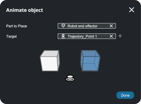
- Animate Object (action)#
Purpose: The Animate Object action automatically moves a motorized joint or part from its current position to a defined position/rotation target. For instance, a robot arm might move from one position to another.
Similar to the placing action, Animate Object pop-up requires two main elements: a part and a target:
Part to Place#
Select a part (an object) in the Hierarchy and drop it in the Part to Place slot. The part must be physicalized first.
Target#
Select the part's Target in the Hierarchy and drop it in the Target slot.
Here again a target can be created by clicking on the + icon if one does not already exist.
Done#
Click to validate, close the pop-up and return to Scenario Builder.
Animate Object Target component#
When selected, the target will show a blue ghost in the Scene View. Use the target's gizmo to move the target to the desired final position/rotation of the part.
When selected, the Target component is displayed in the Inspector panel (image below).
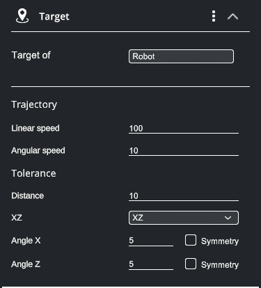
The following parameters control the movement of the part:
Target of#
Name of the linked part. Cannot be modified.
Linear Speed#
Speed at which the object moves along its trajectory toward the target (in meters per second).
Angular Speed#
Speed at which the object rotates to align with the target's orientation (in degrees per second).
Distance#
Defines how close the origin of the part must be to the origin of the target for the action to be considered complete (in meters).
Example: If a cylinder moves slowly but rotates quickly, it will reach its target's rotation quickly but will not validate the action until the distance tolerance is met.
Axis#
Scroll down the list to select the first and second axes to be used for angle tolerance (XY, XZ, YZ),
Angle#
Angular tolerance for the first and second axes (same as for Placing). This defines how closely the direction of the object's first (then second) axes must match the target axes for the action to be completed (in degrees).
Example: If a cylinder moves quickly but rotates slowly, it will reach its target position quickly but will not validate the action until the angular tolerance is met.
Symmetry#
Check the box if the part can be aligned in the axis direction and the opposite direction (symmetrical part, same as for Placing). Leave unchecked if the direction must be respected.
- Watch Media (action)#
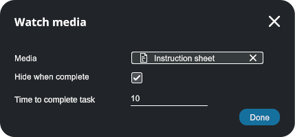
Purpose: The Watch Media action displays a picture or video. Users may be prompted to watch a video or view an image, such as a short video demonstrating how to inspect engine parts
This action requires to import a media file (image or video) in the project first. The image or video will be displayed one time for the user to watch. The user must look at the media for a specified duration to complete the action. Configuration options include:
Media#
Select the media file (image or video) from the Hierarchy panel and drop it in this slot.
Hide when complete#
Enable this option to automatically hide the media once the action is completed. If the option is left unchecked, the screen will remain displayed (displaying the last frame for videos).
Time to Complete Task#
The time for which the user must view the media (for images only; for videos it equals the video length).
Done#
Click to validate, close the pop-up and return to Scenario Builder.
Info
In Simulation mode, videos can currently only be watched when they are inserted into a scenario step (outside of a scenario, coming soon). The video plays once.
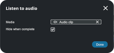
- Listen to Audio (action )#
Purpose: The Listen to audio action plays the sound of an audio clip. Audio instructions, like detailed guidance can be provided at any point.
This action requires to import a media file (audio) in the project first. The user has to listen to the audio clip until the end to complete the action.
Media#
From the Hierarchy, select the audio clip to be played and drop it in the "Media" slot.
Hide when Complete#
Enable this option to deactivate the audio clip when you have listened to it to the end.
Done#
Click to validate, close the pop-up and return to Scenario Builder.
Info
In Simulation mode, audio clips can currently only be listen when they are inserted into a scenario step (outside of a scenario, coming soon). The audio clip plays once.
- Wait (action)#

Purpose: The Wait action adds a timer for a specific duration and pauses for a moment before completing the action. This could be used, for example, to wait for a machine to finish a task before proceeding.
This action is completed once the specified timeout has expired.
Name#
Add an explicit name for the wait action to be displayed in the task list.
Timeout#
Change the timeout value (seconds) directly in the builder pop-up  .
.
Play the Scenario#
Once all your steps have been defined, test your scenario. To do this:
- Close Scenario Builder pop-up.
- Check the User (manipulations are more intuitive in VR).
- Save your project.
- Click Start to run the simulation.
- The scenario starts immediately.
- Complete each action and move forward step by step.