User Interface#
The XRTwin user interface is designed to provide a comprehensive and intuitive workspace for creating and managing your virtual reality simulations. Let's explore the various components of the user interface.
Design mode, Simulation mode or Replay mode?
XRTwin offers three modes: Design mode, Simulation mode and Replay mode.
- From the Launcher, when you open your project, you are in Design mode: users have complete freedom to modify the scene, add objects, and adjust properties.
- From Design mode, after clicking the Start button, you switch in Simulation mode: scene modification is disabled, and objects behave according to physics laws. Click the Stop button to stop the simulation and switch back to Design mode. This will reset the object positions, allowing for further editing and refinement. See Simulation.
- From the Launcher, you can open the Replay mode to watch a recording.
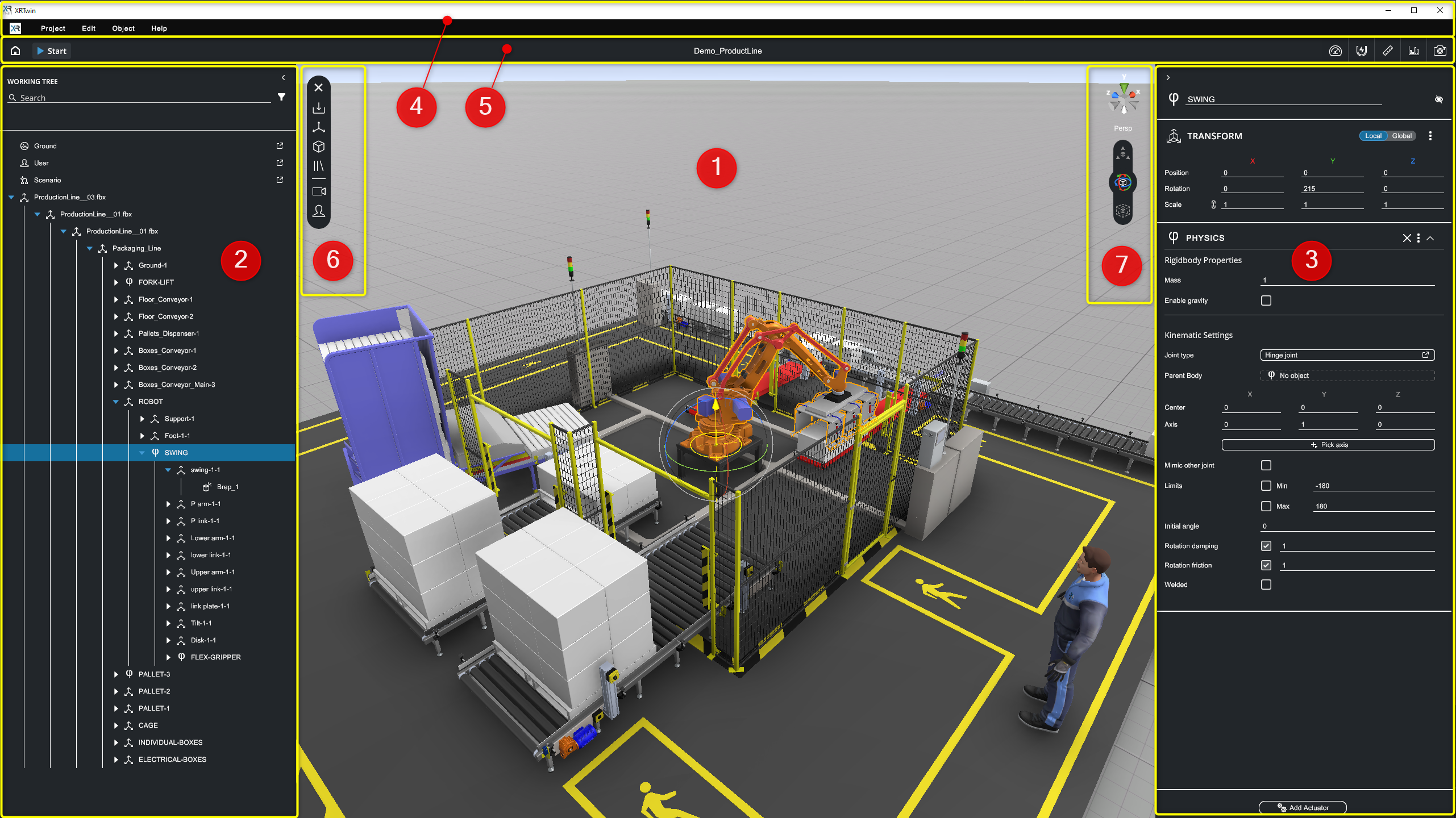
The XR Twin User interface#
1. Scene View#
The central area of the user interface is the Scene View, where all the 3D objects of your simulation are displayed. This is where you can interact with and visualize your virtual environment.
See Scene navigation presets and Object manipulation to learn more about actions you can do in the Scene View.
Shortcuts in Scene View
Click within the Scene View to give it the focus. Then you can:
- Use the F key to center and focus on the selected object. Alternatively, double-click the object.
- Use the arrow keys to adjust the point of view. Use the Left, Right arrows to move it to the left or right (pan). Use the Up and Down arrows to move forward and backward by increments (zoom).
- Use Shift key to enable grid snapping. See Incremental moves.
- Use V key to enable vertex to vertex snapping when translating a node. See Vertex to vertex snapping.
- Use the other global shortcuts.
2. Hierarchy or Working Tree#
Located on the left panel, the Hierarchy panel (labeled Working Tree) provides a hierarchical list of all objects (nodes) in the scene, along with their relationships (parenting).
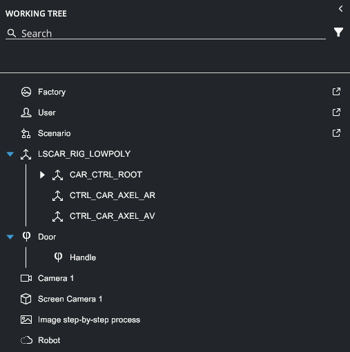
Each node type is represented by an icon, making it easy to identify different elements such as rigid bodies, models, and point clouds (see complete type list below).
Shortcuts in Hierarchy panel
Click in the Hierarchy panel to give it the focus. Then you can:
- Use the F key to center and focus on the selected object in the Scene View.
- Use the arrow keys Left, Right, Up, Down to move between hierarchical levels. Select the next or previous node on same level. Go up to the parent level or down to the child level. Levels expand and collapse automatically.
- Use mouse wheel to scroll the hierarchy list. Keep the cursor flying over the panel.
- Use Ctrl+A keys to Select All.
- Use the other global shortcuts.
Filters#
You can filter the nodes displayed in the Hierarchy panel by name or by object type. The two methods complement each other.
Filter by name  #
#
Enter the first few characters that you want to use as a filter. Only nodes with matching names are displayed. It is not case-sensitive.
Filter by object type  #
#
You can click on the Filter button to open the Filter popup. Select or deselect the proposed object types to filter the nodes, which will improve organization and navigation.
- Only the checked types are displayed.
- Click Reset to uncheck all object types.
- If no type is checked, the filter by object type is inactive and all types are displayed.
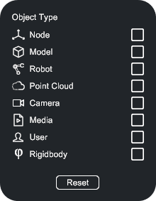
- Node: All empty nodes (without geometry)
- Model: All 3D models (a node with geometry)
- Robot: All robots.Coming soon
- Point Cloud: All imported point clouds (see Import Point clouds)
- Camera: All additional virtual cameras
- Media: All imported media (audio, video or image sources, see Imported Media files)
- User: The current User
- Rigidbody: All objects with physical properties (see Physics and interactions)
- Reset: Click to clear all filters.
Relationships#
The Hierarchy panel allows you to modify the relationships between objects by re-parenting them.
- Change parent: drag a node and drop it on its new parent node.
- Insert between children: drag the node and drop it in between two consecutive children.
- Bring to root level: drag a node and drop it in an empty space below the hierarchy.
Node contextual menu#
Use the node Contextual menu to quickly perform the available actions (context-dependent). Right-click on a node and select an action from the contextual menu. If collapsed, expand the hierarchy first to reveal the node.
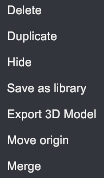
Delete#
Remove selected object from scene (shortcut Ctrl+Del). Not-undoable.
Duplicate#
Duplicate selected object (shortcut D). An offset is provided to make it easy to select and move.
Hide / Show#
Hide or show the current object (shortcut Ctrl+H). If an object is hidden, its physical behaviors are inactivated and ignored in the simulation (activated and taken in account, respectively).
Save as library#
Save the selected object (in the hierarchy graph, if applicable) and all of its children to any directory of your choice, with the .xrlib extension.
Tip
It is recommended that you create a library folder accessible from all your projects to store reusable objects, such as pallets, forklifts, screwdrivers, silhouettes for scale, workbenches, baskets, etc.
You can then add these objects to any project later: from the main menu, select Object > Add > Add from library.
Export 3D Model#
Export the selected object node and all of its children (if applicable) to any directory of your choice. Multiple CAD formats are available (drop-down Type field).
Move origin#
Edit the origin of the selected part. XRTwin will make remarkable suggestions based on the object's topology, such as centers and perpendiculars. See Move part origin.
Merge#
A local process that combines all the child nodes of the selected parent into a single "Group" entity, reducing the number of draw calls and improving performance. This action can be reversed: right-click on the "Group" node and select "Unmerge" in the contextual menu. See Merge static objects
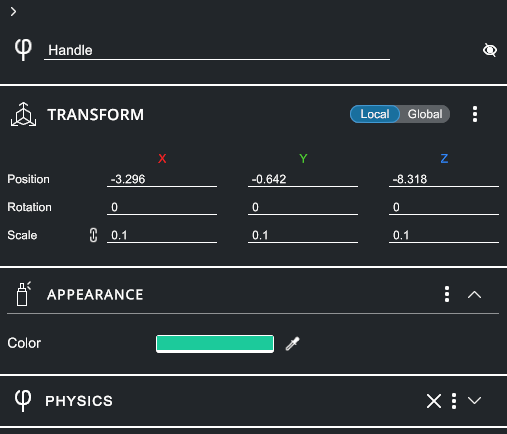
3. Property Panel#
The right panel of the user interface is the Property Panel. It provides contextual information about the selected objects such as their position, appearance, and physics properties.
The Property Panel allows you to enable/show or disable/hide the selected object, change its name, and add or modify its attributes to fine-tune its behavior.
- Click

 buttons to disable/hide or enable/show selected object(s) (toggle).
 - Click

 buttons to expand/collapse sections and show all the properties (toggle).
 - Click three-dot menu
 to Copy or Paste the component's values. See Copy Paste object properties below.
 - Click
 button to remove a component (if available).
Shortcuts in Property Panel
In the Property Panel, click in an input field to give it the focus. Then,
- Use the Tab key to jump from one input field to the next one.
Copy Paste object properties#
In Design mode, you can copy components properties from current object and paste them onto another.
Copy and paste in Property panel
Each component type uses a specific and unique copy buffer. So you can copy Transform, Physics and Appearance properties successively, for example. Then, you can select another object, go to corresponding component type (must be the same type, here Transform, Physics or Appearance) and paste successively the properties.
Each buffer is updated when you copy again.
To copy and paste multiple components when in Design mode:
- Select an object.
- In the Inspector panel, in the source component, click the mini-menu button, then select Copy.
- If needed, do this for other relevant source components, one after another.
- Select another object.
- In the corresponding target component (must be the same), click the mini-menu button again and select Paste. Values are replaced.
- Repeat for each other relevant target component, if applicable.
How do I copy transform values from Simulation mode to Design mode?
To copy transform values (Translation, Rotation, Scale) from Simulation mode to Edition mode, see Copy Transform in simulation workflow in What can I do in Simulation mode section.
4. Menu Bar#
Located to the left of the Menu Bar, you will find the main menu with Project, Edit, Object, and Help drop-down menus.
Project menu#
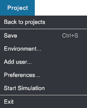
Back to projects#
Returns to the Launcher. Same as Home button  .
.
Save#
Save your project. Shortcut Ctrl+S.
Environment...#
Select an other background for your scene.
Add user...#
Guided user selection. Based on the hardware you want to use.
Preferences...#
Select user settings at project level.
Start Simulation#
Launch the simulation session. Same as Start button  .
.
Exit#
Quit XR Twin. You will be prompted to save changes before you confirm exit.
Edit menu#
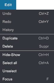
Undo#
Currently only transforms can be undone. Shortcut Ctrl+Z.
Redo#
Currently only transforms can be redone. Shortcut Ctrl+Y.
History#
Coming soon.
Duplicate#
Duplicate selected object. An offset is provided to make it easy to select and move. Shortcut Ctrl+D.
Delete#
Remove selected object from scene (not-undoable). Shortcut Del.
Hide-Show#
Hide or show the current object. Shortcut Ctrl+H.
Info
If an object is hidden (shown), its meshes and physical behaviors are inactivated and ignored in the simulation (activated and taken into account, respectively).
Select all#
Select all the nodes. Shortcut Ctrl+A.
Unselect#
Clear selection. Shortcut Esc.
Focus#
Focus the camera on selected object. Shortcut F.
Info
During the focus action, the object is centered in the scene view, the zoom sensitivity is adjusted according to the object's size, and the orbit rotation center is set at the object's center of mass.
Object menu#
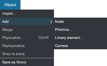
Import...#
Import your files in your scenes. Multiple formats are available for CAD and Mesh files (see Import CAD files, Point clouds (see Import point clouds) or media files (images, audio files and video movies, see Import media files.
Add Node#
Add an empty node to your scene.
- Select one node: empty node added as child.
- Multi-select some nodes: empty node added as child of the first selected. Other selected objects are ignored.
- No selection: empty node is added at root level.
Add Primitive...#
Add primitives (cube, sphere, capsule...) as child as the current node or at root level (same rules as above).
Add Library element...#
Add an object that you previously saved in a *.xrlib file to your scene. All properties are restored.
-
Select one node: selected node and its children are replaced by the element. The root node of the element gets the same transforms as the selected node.
-
Multi-select some nodes: selection is ignored and the element is added at root level.
- No selection: element is added at root level.
Add Camera#
Add a virtual camera and its virtual screen in the scene. The video stream from this camera is displayed on the virtual screen. You can also choose to display it on one of the additional real screens managed by your computer.
Merge#
See context menu.
Physicalize...#
Guide you to select the physical behavior you want to apply on selected object(s). Shortcut Ctrl+P.
Dephysicalize#
The PHYSICS component is removed from selected object(s). All physical behaviors are deleted. Cannot be undone.
Save as Library#
See context menu.
Help menu#
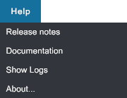
Release notes#
Open the release notes page in your web browser. See Release notes.
Documentation#
Open XRTwin online documentation in your web browser. See XR Twin Documentation.
Show Logs#
Open the C:\Users\username\AppData\LocalLow\LSGROUP\XRTwin folder where you can find the application log files Player.log (the most recent session log file) and Player-prev.log (the previous session log file).
Sending these two files, along with a description of the issues you are experiencing, to support can help our team identify the problem. Other log files are also present in this folder.
About...#
Open the "About" window where you will find version number, documentation and release notes links, copyright and more.
5. Tool Bar#
The top section of the user interface features the Tool Bar, which contains several essential options.

- to go back Home, to the Project Launcher screen.
-
 to start and stop the simulation.
 - In the center is the project name (here Demo_ProductLine).
Tools 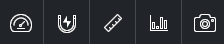 #
#
At the right side, you will find various tools such as (from left to right) Optimize tool, Snapping tool, Measuring tool, Statistics panel and Make Screenshots, enhancing your control and analysis capabilities.
Optimize scene tool  #
#
Merge static objects. See Merge static objects section for how to and restrictions.
Snap object tool  #
#
Stick selected object to another. First, click to select the face of the source object to be snapped. Then, fly over the target face (must be on another object. If needed, use the shortcut I to invert snapping direction. Click to validate.
Measure tool  #
#
Measure distances. Click on the first point, then the second. Short distance is indicated in millimeters. To decompose measures on XYZ axes, from main menu go to Project>Preferences>Graphics and check Show measure XYZ decompo. Fly over and click on the trash can to delete. The measurements persist between Design and Simulation modes, but are not saved with your project. For measures in VR, see the Measure tool in the VR Menu.
Show Statistics panel  #
#
Display the Statistics panel. In Design mode, the panel displays the graphics performance (frame rate) and the number of objects, polygons and rigid bodies in the scene.
In Simulation mode, it displays the physics update duration / default allowed time (hold it below allowed time for maximum physical frame rate). In milliseconds (ms).
Take Screenshots tool  #
#
Use the Take Screenshot tool to capture images. See Take screenshots for tips and quick images folder access.
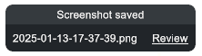
Easily find your screenshots#
Screenshots are saved in the Screenshots subfolder within your projectID directory. To easily open this folder, follow one of this tips.
To open the screenshots folder immediately:
Immediately after taking a screenshot, a "capsule" appears at the bottom of your Scene view (see image below).
- Click the “Review” link to immediately open the
Screenshotsfolder in your File Explorer.
To open the screenshots folder later:
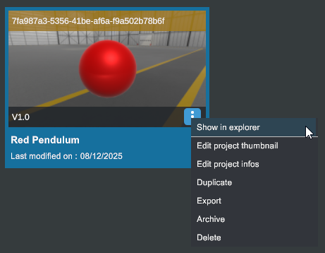
- Return to the Launcher and press Alt+Shift+F9 to reveal advanced options.
- Select your project card, open its mini-menu and click Open in explorer.
Your File Explorer will open with your current "projectID folder" selected. The name is such as7fa987a3-5356-41be-af6a-f9a502b78b6f. - Open this folder, then open the
Screenshotssubfolder.
All your screenshots are here (if you took any).
Do not inadvertently change ProjectThumbnail.png. This image is used as background for the project card.
6. Quick Access bar#
Located above the Scene View on the left, the Quick Access bar offers quick and convenient access to frequently used operations. This bar includes options to import objects and elements from the library, change the user type (Desktop or VR), and create primitive objects for quick prototyping and scene setup.
Click the Quick Access button  to expand.
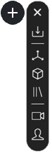
Import CAD files and more  #
#
See Object > Import....
Create an empty node  #
#
See Object > Add > Node.
Add a primitive  #
#
See Object > Add > Primitive....
Add a library element  #
#
See Object > Add > Library element....
Add a camera  #
#
Change the user  #
#
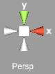
7.1 View Selector#
Located at the top right of the scene view, the View Selector tool provides essential functionality for adjusting the camera view switching between predefined camera views such as top, side, and left providing a convenient way to view the scene from different perspectives or orthogonal projections.
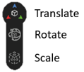
7.2 Manipulation toolbar#
Located below the View Selector, the Manipulation toolbar provides essential functionality for manipulating objects. Click on the icons to switch between translation, rotation, and scale modes and manipulate selected object(s)' gizmos with your mouse. You can also use the W, E and R keyboard shortcuts.
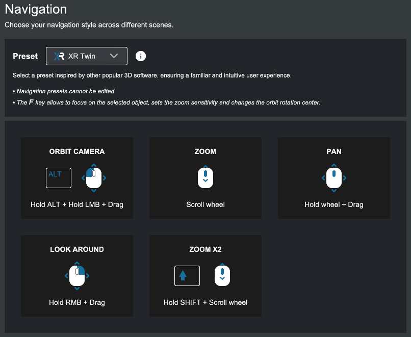
Scene navigation presets#
XR Twin offers several presets for mapping other software navigation styles. The keyboard and mouse shortcuts you use to move the viewpoint depend on the selected preset. Default preset is XR Twin style (see the XR Twin shortcuts in the image below).
If you’re accustomed to CAD design software, you might prefer to adjust your navigation preferences. XRTwin offers preset navigation styles tailored to popular CAD tools.
For beginners
We recommend starting with XR Twin’s default navigation style preset for the best experience.
You can set your preferred navigation preset globally, at application level, ensuring all new projects default to your chosen style, or you can set it at project level.
To select your global favorite navigation preset from the Project Launcher:
- From the left panel, select Settings to display the Settings panel.
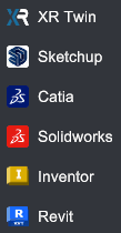
- In the Navigation section, pull down the Preset dropdown list.
- Select the software whose navigation shortcuts you want to use: Sketchup, Catia, Solidworks, Inventor or Revit, or stick with the default XR Twin preset.
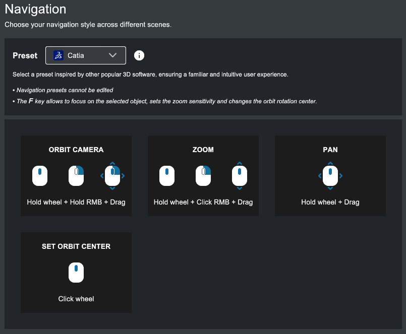
- Each preset displays its associated shortcuts (see XR Twin and Catia presets below).
- Your choice will apply to all new projects.
To select per project your favorite navigation preset from an opened project:
- With your project opened in EDITION Mode,
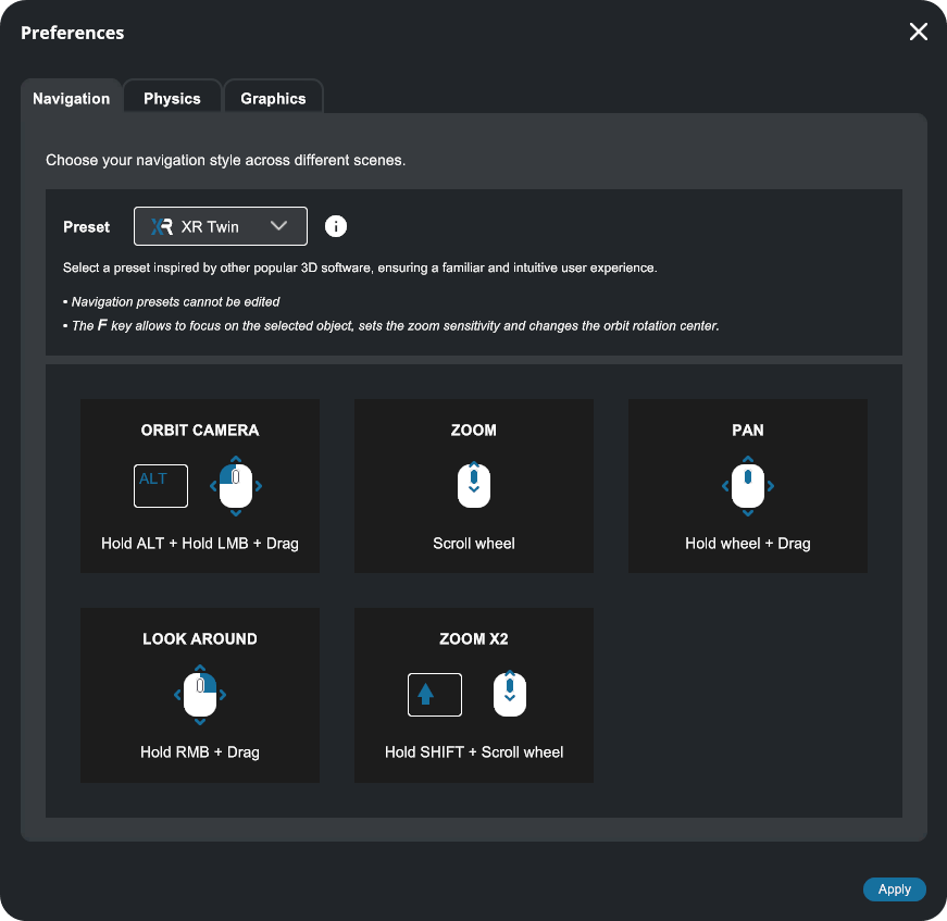
- From the main menu, go to Project>Preferences... to open the Preferences window.
- Select the Navigation tab.
- Next to Preset, expand the drop-down menu and select your favorite navigation preset (same as above).
- Click Apply to save and close the window.
- Your choice will only apply to the current project.
Object manipulation#
Located at the node reference point in the scene (pivot point), the move gizmos switch between translation, rotation and scale modes for the selected object, depending Manipulation Bar current option. The axes' direction depends on the current option of Local/Global and the hierarchy's parent transforms.
Translation gizmo#
The translation gizmo represents the three local or global XYZ translation axes, as well as the three corresponding planes.
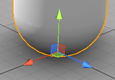

- Drag one of the three colored arrows (RGB) with the mouse to move the node in the desired direction (the X, Y, and Z axes, respectively).
- At the base of the gizmo, you will find colored squares (RGB). Click with the mouse to drag the node onto the corresponding plane (XZ, ZY, XY, respectively).
Rotation gizmo#
The rotation gizmo represents the three possible rotations around the local or global XYZ axes.
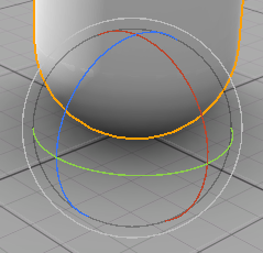

- Rotate one of the colored wheels (RGB) with the mouse to rotate the node around the desired axis (XYZ, respectively).
Scale gizmo#
The scale gizmo represents the three possible scaling options, according to the local or global XYZ axes.
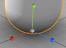

- Drag one of the colored cubes (RGB) with the mouse to stretch the node on the selected axis (XYZ, respectively).
- At the base of the gizmo you will find a white cube. Click on it with the mouse and drag to perform a uniform scale change on all three axes simultaneously.
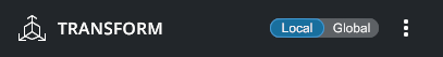
Local mode / Global mode#
If the node's TRANSFORM is in Local mode, then the gizmo orients itself according to the object's local coordinate system, which takes into account the orientation of its parents.
However, if the node's TRANSFORM is in Global mode, then the gizmo orients itself according to the scene's global coordinate system, regardless of the orientation of its parents.
Incremental moves#
Holding down the Shift key when you move a gizmo, you can perform incremental moves:
- Incremental translations (default steps of 0.5 m).
- Incremental rotations (default steps of 10°).
- Incremental scalings (default steps of x0.5).
Vertex to Vertex snapping#
To translate a node, you can use the V key to enable the Vertex to Vertex snapping mode.
- Select a source object that has geometry.
- Fly over one of the selected object's vertices. You will see the gizmo jump from place to place.
- Click to select it as the source vertex.
- Drag to translate the object, snapping its source vertex to a target vertex.
Vertex to Vertex restriction
Only a vertex located on another object can be a valid target vertex.
The XRTwin user interface is thoughtfully designed to minimize the time required to create incredible and realistic simulations. Experience the efficiency and speed of XRTwin as you bring your virtual reality visions to life in a fraction of the time it would traditionally take.